Typical issue found:
"I power the modem from 5V power source connected to the Vin pad ("LiPOL powering schema"). The wiring was done according to the manufacturer website. The manufacturer library was used.
The module operates correctly for ~6-10 seconds, and after that the
LiPO LED (RED) starts flashing with high frequency and the module does not respond to AT
commands. If I'll RESET it, the modem will opperate again for ~6-10 seconds, later the
YELLOW AND GREEN LEDs goes off and the module did not responde to AT command (timeout)."
Why this happen:
In boot and in transmission mode, all modems require some important current spikes (up to 2A for certain models). In such cases, the voltage will drop - sometimes under safe functioning limit - and the modem may unexpectally SHUTDOWN.
The LiPO battery or the super-capacitor have the role of storage of energy and to fulfill the spyke current requests (keeping the voltage almost stable at modem input).
5V powering info ("LiPOL powering schema") and references

Step 1:
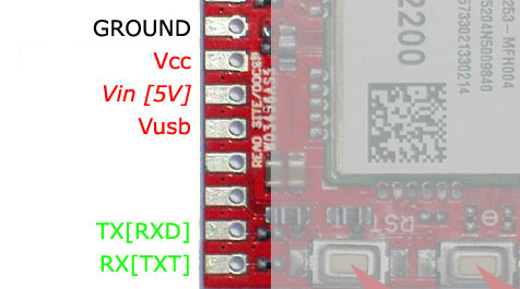
All itbrainpower.net modular modem shield type (c-uGSM, h-nanoGSM, d-u3G or l-LTE) and second generation modular modems (u-GSM familly) share the same ITBPMM interface. First of all, identify on your itbrainpower.net modular modem following pads:
- GROUND - named bellow MDM-GND
- Vin[5V] - named bellow MDM-5V
Right image - c-uGSM shield.
Verify to have wired the 5V power supply pole to MDM-5V and the power supply GND to MDM-GND. This apply also for powering fron USB 5V (just connect Vin pad to Vusb pad).
Step 2:
Just to make the long story short: Identify the modems LiPO battery pads. Solder the LiPO battery connector.
Connect the LiPO battery to the modem. Respect the polarity!
DONE!
Alternative a. The LiPO can be connected to Vcc and GND pads (on ITBPMM interface). LiPO+ must be wired to Vcc and LiPO- to the GND.
Alternative b. The LiPO battery can be replaced with one super-capacitor having 1F / 5V, LOW ESR [<200mOhm].
References:
- itbrainpower.net modular modem block schema (c-uGSM, h-nanoGSM, d-u3G or l-LTE)
- u-GSM block schema (u-GSM familly)
SPECIAL HINT for u-GSM shield equipped with BG96 or BC95G:
If the 2G/GSM mode it is restricted in software (the BG96 module opperates in LTE CATM1 or NB IoT mode only), the LiPO battery or the super-capacitor may be replaced with one 1000-2200 uF /6.3V Low ESR capacitor. This is valid always for BC95G module (NB IoT only). See how here.