About SMS relay controller Arduino project
Very low signal area? Simple remote control solution required? Tired of unexpected complications? In this IoT driven world, some oldies but goldies implementations as this relay(s) controlled by SMS still takes the spotlight. Forget fancy implementation, just KISS!
Project required time*
- Hardware side: around 5-10 minutes.
- Arduino classes install: 5-10 minutes.
- Arduino software side: 5 minutes.
SMS relay controller - required shields and materials
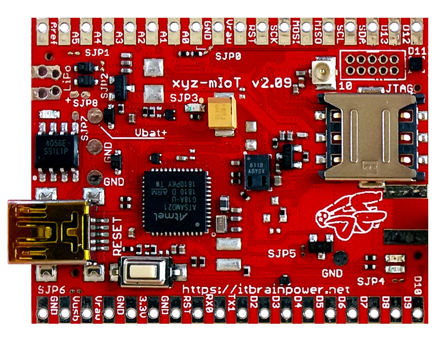
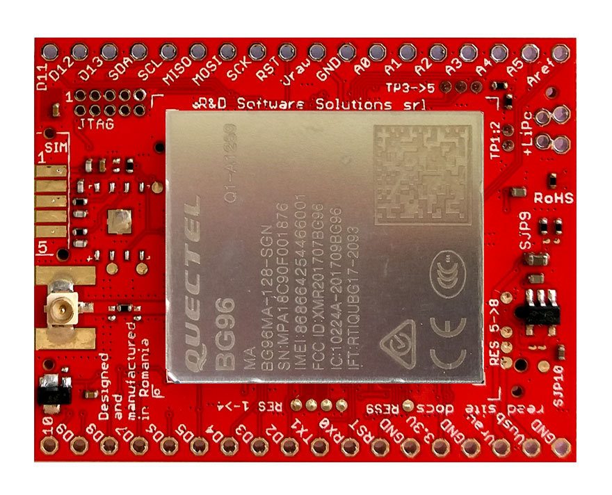
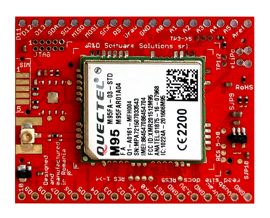
* 1 pcs. x xyz-mIoT by itbrainpower.net equipped with Quectel M95FA P/N: XYZMIOT209#M95FA-UFL-0000000 - [BG96 version - P/N: XYZMIOT209#BG96-UFL-0000000 can be use as well]
* 1 pcs. x 1 cell LiPO battery
* 1 pcs. x GSM embedded antenna
* 1 or 2 pcs. x 2 x RELAY shield 5V - we used the Polulu 2-Channel SPDT Relay Carrier with 5VDC Relays
* 1 pcs. 5V power wall adapter
* connecting wires
Additional hardware references
SMS relay controller hardware integration (wiring)
First, identify if your relays are 5V or 12V compliant! For boards having 5V relays, wire as bellow:
 xyz-mIoT by itbrainpower.net shield wiring with two relays - 5V - board
HINT, for 12V relays:
* RELAY shield Vin pin (in above picture, it's the RED wire, on the right side, marked +5V) should be connected to +12V power source and the GND pin should be connected to both xyz-mIoT GND and 12V power source GND.
SMS relay controller Arduino software
a. download xyz-mIoT shields Arduino class from: here. Expand the archive and follow the install instructions.
b. Make a folder named "SMS-relay-controller".
Copy the code bellow, paste it one new file and save the file as "SMS-relay-controller.ino" in the folder created in previously or, you may
download it from here (right click & save as): SMS relay controller - control relay(s) via SMS Arduino code
| 1 | /* |
| 2 | SMS-relay-controller.ino v 0.4/20190712 - for xyz-mIoT shields |
| 3 | COPYRIGHT (c) 2015-2019 Dragos Iosub / R&D Software Solutions srl |
| 4 | |
| 5 | You are legaly entitled to use this SOFTWARE ONLY IN CONJUNCTION WITH xyz-mIoT DEVICES USAGE. Modifications, derivates and redistribution |
| 6 | of this software must include unmodified this COPYRIGHT NOTICE. You can redistribute this SOFTWARE and/or modify it under the terms |
| 7 | of this COPYRIGHT NOTICE. Any other usage may be permited only after written notice of Dragos Iosub / R&D Software Solutions srl. |
| 8 | |
| 9 | This SOFTWARE is distributed is provide "AS IS" in the hope that it will be useful, but WITHOUT ANY WARRANTY; without even the implied |
| 10 | warranty of MERCHANTABILITY or FITNESS FOR A PARTICULAR PURPOSE. |
| 11 | |
| 12 | IMPORTANT NOTICE! |
| 13 | Before use xyz-mIoT shields, you must download and install "xyz-mIoT shields Arduino class" from https://itbrainpower.net/downloads#xyz-mIoT |
| 14 | |
| 15 | In order to compile this code following additional files are required: "XYZMIOT_basic_lbr.h", "XYZMIOT_basic_lbr.ino", "XYZMIOT_SMS_lbr.h" |
| 16 | and "XYZMIOT_SMS_lbr.ino". Those files can be found in "xyz-mIoT kickstart for Arduino" available for download at: |
| 17 | https://itbrainpower.net/downloads#xyz-mIoT |
| 18 | |
| 19 | Copy this four file in the same folder where is this source file (SMS_relay_controller.ino)! |
| 20 | |
| 21 | |
| 22 | Dragos Iosub, Bucharest 2019. |
| 23 | http://itbrainpower.net |
| 24 | */ |
| 25 | |
| 26 | //#define modemType BG96 // choose this for xyz-mIoT equipped with BG96 shield |
| 27 | #define modemType M95FA // choose this for xyz-mIoT equipped with M95FA shield |
| 28 | |
| 29 | static char phoneNumber[15] = "0700111222"; //replace with your destination number |
| 30 | //#define FourRelays //remove comment to use it with 4 relays output |
| 31 | |
| 32 | #define OutPort0 8 //Arduino digital port used to drive Relay0 |
| 33 | #define OutPort1 9 //Arduino digital port used to drive Relay1 |
| 34 | #define OutPort2 10 //Arduino digital port used to drive Relay2 |
| 35 | #define OutPort3 11 //Arduino digital port used to drive Relay3 |
| 36 | |
| 37 | |
| 38 | |
| 39 | //#define atDebug //remove comment if you want to supervise modem chat in Serial Monitor |
| 40 | //#define SMSLibDebug //remove comment if debug SMS it's required |
| 41 | |
| 42 | |
| 43 | static char notunderstand[74] = "? relay0,relay1,relay2,relay3 >> 1 ->activate relay, 0 ->release relay"; |
| 44 | static char executed[40] = " cmd executed"; |
| 45 | static char boot[13] = "BOOT EVENT "; |
| 46 | |
| 47 | |
| 48 | |
| 49 | /*#####NO REALLY NEED TO CHANGE PARAMS BELLOW#####*/ |
| 50 | #define agsmSerial Serial |
| 51 | #define BUFFDSIZE 1024 |
| 52 | |
| 53 | #include "Arduino.h" |
| 54 | #include "XYZMIOT_basic_lbr.h" |
| 55 | #include "XYZMIOT_SMS_lbr.h" |
| 56 | //#include "modems_network.h" |
| 57 | |
| 58 | #define BUFFDSIZE 1024 //used by modem library |
| 59 | |
| 60 | |
| 61 | char ch; |
| 62 | char buffd[BUFFDSIZE]; |
| 63 | char readBuffer[200]; |
| 64 | int state=0, i=0, powerState = 0; |
| 65 | |
| 66 | |
| 67 | void procRespose(char* msg){ |
| 68 | memset(readBuffer,0x00,sizeof(readBuffer)); |
| 69 | sprintf(readBuffer, "%s", msg); |
| 70 | SerialUSB.println(readBuffer); |
| 71 | SerialUSB.flush(); |
| 72 | delay(150); |
| 73 | sendSMS(phoneNumber, readBuffer); //confirm command |
| 74 | delay(100); |
| 75 | } |
| 76 | |
| 77 | void setup(){ |
| 78 | |
| 79 | pinMode(OutPort0, OUTPUT); //configure the Dxx as output |
| 80 | pinMode(OutPort1, OUTPUT); //configure the Dxx as output |
| 81 | digitalWrite(OutPort0, 0); |
| 82 | digitalWrite(OutPort1, 0); |
| 83 | #if defined(FourRelays) |
| 84 | pinMode(OutPort2, OUTPUT); //configure the Dxx as output |
| 85 | pinMode(OutPort3, OUTPUT); //configure the Dxx as output |
| 86 | digitalWrite(OutPort2, 0); |
| 87 | digitalWrite(OutPort3, 0); |
| 88 | #endif |
| 89 | |
| 90 | agsmSerial.begin(115200); |
| 91 | SerialUSB.begin(115200);//1ms |
| 92 | delay(3000); |
| 93 | |
| 94 | clearagsmSerial(); |
| 95 | clearSerial(); |
| 96 | delay(10); |
| 97 | |
| 98 | modemHWSetup(); //configure Arduino IN and OUT to be used with modem |
| 99 | |
| 100 | SerialUSB.flush(); |
| 101 | agsmSerial.flush(); |
| 102 | |
| 103 | SerialUSB.println(F("xyz-mIoT boot..")); |
| 104 | SerialUSB.flush(); |
| 105 | |
| 106 | |
| 107 | powerOnModem(); |
| 108 | |
| 109 | clearBUFFD(); |
| 110 | while(strlen(buffd)<1){ |
| 111 | getIMEI(); |
| 112 | delay(500); |
| 113 | } |
| 114 | |
| 115 | ready4SMS = 0; |
| 116 | ready4Voice = 0; |
| 117 | |
| 118 | setupMODEMforSMSusage(); |
| 119 | |
| 120 | SerialUSB.println(F("xyz-mIoT ready.. let's proceed")); |
| 121 | SerialUSB.flush(); |
| 122 | delay(100); |
| 123 | |
| 124 | procRespose((char*)boot); //send SMS |
| 125 | |
| 126 | } |
| 127 | |
| 128 | int checkSMSAuthNo(int SMSindex){ |
| 129 | int ret = 0; |
| 130 | clearBUFFD(); |
| 131 | if(ready4SMS != 1) setupMODEMforSMSusage(); |
| 132 | if(totSMS<1) listSMS(); |
| 133 | if(SMSindex > noSMS || SMSindex < 1) return -1; |
| 134 | |
| 135 | clearagsmSerial(); |
| 136 | agsmSerial.print("AT+CMGR=");//send command to modem |
| 137 | agsmSerial.print(SMSindex);//send command to modem |
| 138 | agsmSerial.println(",0");//send command to modem |
| 139 | delay(1); |
| 140 | |
| 141 | readline();//just 2 remove modem cmd echo |
| 142 | readline();//just 2 read second line ==> (containing OK / +CMS ERROR / SMS header) |
| 143 | |
| 144 | SerialUSB.println(buffd); |
| 145 | |
| 146 | if(strstr(buffd, phoneNumber)) ret = 1; |
| 147 | clearBUFFD(); |
| 148 | clearagsmSerial(); |
| 149 | |
| 150 | return ret; |
| 151 | } |
| 152 | |
| 153 | void loop(){ |
| 154 | //process SMS commands - start |
| 155 | listSMS(); //find the last used SMS location |
| 156 | clearagsmSerial(); |
| 157 | int cnt; |
| 158 | cnt = noSMS; |
| 159 | while (cnt>0){ |
| 160 | if(checkSMSAuthNo(cnt)<1){ |
| 161 | deleteSMS(cnt); |
| 162 | SerialUSB.println("no auth no"); |
| 163 | clearBUFFD(); |
| 164 | } |
| 165 | else{ |
| 166 | readSMS(cnt); //the SMS content will be returned in buffd |
| 167 | SerialUSB.print(F("SMS content: "));SerialUSB.flush();delay(50); |
| 168 | SerialUSB.println(buffd);SerialUSB.flush();delay(50); |
| 169 | } |
| 170 | //here process SMS the content - start |
| 171 | |
| 172 | delay(50); |
| 173 | clearagsmSerial(); |
| 174 | delay(50); |
| 175 | |
| 176 | if(strlen(buffd) > 0){ //non empty SMS |
| 177 | int OutputVal0 = -1; |
| 178 | int OutputVal1 = -1; |
| 179 | |
| 180 | #if defined(FourRelays) |
| 181 | int OutputVal2 = -1; |
| 182 | int OutputVal3 = -1; |
| 183 | sscanf(buffd, "%i,%i,%i,%i", &OutputVal0, &OutputVal1, &OutputVal2, &OutputVal3); |
| 184 | clearBUFFD(); |
| 185 | sprintf(buffd, "%i,%i,%i,%i >> %s", OutputVal0, OutputVal1, OutputVal2, OutputVal3, (char*)executed); |
| 186 | #else |
| 187 | sscanf(buffd, "%i,%i", &OutputVal0, &OutputVal1); |
| 188 | clearBUFFD(); |
| 189 | sprintf(buffd, "%i,%i >> %s", OutputVal0, OutputVal1, (char*)executed); |
| 190 | #endif |
| 191 | |
| 192 | SerialUSB.println(buffd); |
| 193 | |
| 194 | #if defined(FourRelays) |
| 195 | if(OutputVal0<0 || OutputVal1<0 || OutputVal2<0 || OutputVal3<0){//check parse message success |
| 196 | #else |
| 197 | if(OutputVal0<0 || OutputVal1<0){//check parse message success |
| 198 | #endif |
| 199 | procRespose((char*)notunderstand); |
| 200 | //SerialUSB.println("error"); |
| 201 | } |
| 202 | else{ |
| 203 | digitalWrite(OutPort0, OutputVal0); |
| 204 | digitalWrite(OutPort1, OutputVal1); |
| 205 | #if defined(FourRelays) |
| 206 | digitalWrite(OutPort2, OutputVal2); |
| 207 | digitalWrite(OutPort3, OutputVal3); |
| 208 | #endif |
| 209 | procRespose(buffd); |
| 210 | //SerialUSB.println("fine"); |
| 211 | } |
| 212 | |
| 213 | deleteSMS(cnt); //free the SMS location |
| 214 | } |
| 215 | //here process SMS the content - end |
| 216 | clearBUFFD(); |
| 217 | clearagsmSerial(); |
| 218 | cnt--; |
| 219 | } |
| 220 | //process SMS commands - stop |
| 221 | delay(500); |
| 222 | } |
| 223 | |
| 224 |
c. download xyz-mIoT kickstart for Arduino from: here. Expand the archive and copy "XYZMIOT_basic_lbr.h", "XYZMIOT_basic_lbr.ino", "XYZMIOT_SMS_lbr.h" and "XYZMIOT_SMS_lbr.ino" in previous folder.
d. In line 29, update the phoneNumber value with your phone number (will act as MASTER number - only messages received from this number will be processed). Save.
e. Select xyz-mIoT shield board and programming port.

REMINDER: In order to be able to upload the code, you must press twice (fast) xyz-mIoT shield RESET switch [the board will enter programming mode].
f. Now, you may compile and upload the code to your xyz-mIoT shield. Debug messages can be seen in Serial Monitor [115200bps,8N,1].

- only messages from MASTER number will be interpreted/executed. Other messages will be deleted from SIM card.
SMS commands accepted by relay controller:
- 2 relays version send relay0,relay1 where relayX can be 1 for activate relay, or 0 for release relay [Eg.: 1,0 - meaning: Relay 0 activated and Relay 1 released]
- 4 relays version send relay0,relay1,relay2,relay3 where relayX can be 1 for activate relay, or 0 for release relay
Relay controller originated / reply messages:
- at BOOT, the relay controller will send "BOOT" message to MASTER number;
- in case of accurate commands, the controller will reply with received command + content defined in variable executed;
- in case of messages parsing error, the controller will reply with a sort of help message [defined by notunderstand content];
TUTORIAL PROVIDED WITHOUT ANY WARRANTY!!! USE IT AT YOUR OWN RISK!!!!