LTE CATM / NB-IoT development kit(s) - presentation
itbrainpower.net LTE CAM + NB-IoT development kit - all you need to develop your battery operated LTE CATM or NB-IoT IoT node.
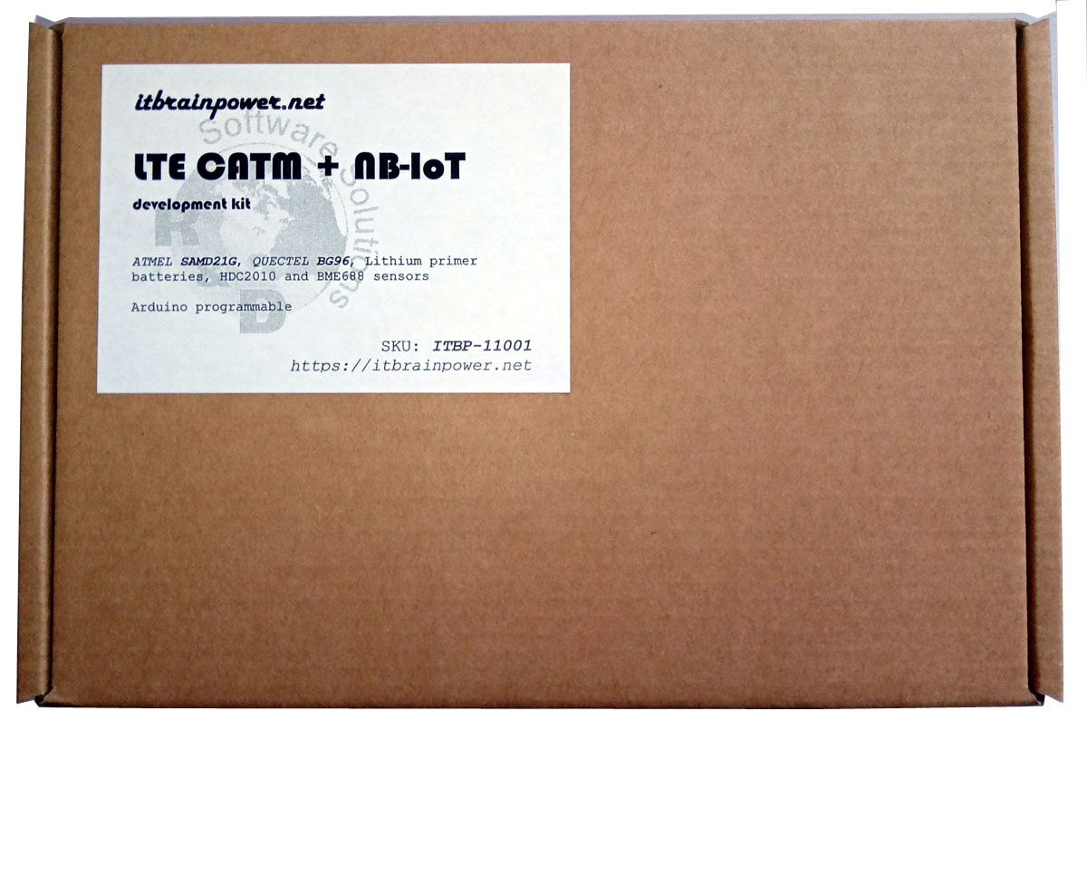
LTE CATM + NB-IoT development kits
SKU: ITBP-11001 - ATMEL SAMD21G + QUECTEL BG96.
- LTE CATM and NB IoT supported + 2G fall back;
- global modem coverage (Europe, North America and other);
- multi-constellation (GPS, GALILLEO, GLONASS) GNSS engine embedded;
- ATMEL SAMD21G ARM0 micro-controller, Arduino programmable;
- optimized for Lithium primer battery powered operation;
- ultra low deep sleep current ~7-9uA (ultra low power mode with RTCC and 1 x DIGITAL port interrupts);
- TH (HDC2010), gas & AI(BME688), REED and TILT sensors;
- Arduino programmable. LTE CATM, NB IoT, GNSS, sensors and ultra low power examples.
SKU: ITBP-11002 - ATMEL SAMD21G + QUECTEL BG95-M2.
- LTE CATM and NB IoT supported - 2G not supported;
- global modem coverage (Europe, North America and other);
- multi-constellation (GPS, GALILLEO, GLONASS) GNSS engine embedded;
- ATMEL SAMD21G ARM0 micro-controller, Arduino programmable;
- optimized for Lithium primer battery powered operation;
- ultra low deep sleep current ~7-9uA (ultra low power mode with RTCC and 1 x DIGITAL port interrupts);
- TH (HDC2010), gas & AI(BME688), REED and TILT sensors;
- Arduino programmable. LTE CATM, NB IoT, GNSS, sensors and ultra low power examples.
SKU: ITBP-11003 - ATMEL SAMD21G + QUECTEL BG95-M3.
- LTE CATM and NB IoT supported + 2G fall back;
- global modem coverage (Europe, North America and other);
- multi-constellation (GPS, GALILLEO, GLONASS) GNSS engine embedded;
- ATMEL SAMD21G ARM0 micro-controller, Arduino programmable;
- optimized for Lithium primer battery powered operation;
- ultra low deep sleep current ~7-9uA (ultra low power mode with RTCC and 1 x DIGITAL port interrupts);
- TH (HDC2010), gas & AI(BME688), REED and TILT sensors;
- Arduino programmable. LTE CATM, NB IoT, GNSS, sensors and ultra low power examples.
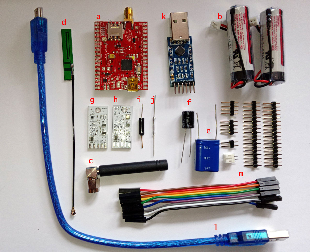
ITBP-11001/ITBP-11002/ITBP-11003 LTE CATM + NB-IoT development kits - what's inside the box
a. ITBP-11001 - itbrainpower.net xyz-mIoT w. BG96 Ultra Low Power version (~7-9uA deep sleep) [SKU ITBP-4083] Lithium Primer battery only, SMA (LTE side), uFL (GNSS side) - 1pcs.;
a. ITBP-11002 - itbrainpower.net xyz-mIoT w. BG95-M2 Ultra Low Power version (~7-9uA deep sleep) [SKU ITBP-4081] Lithium Primer battery only, SMA (LTE side), uFL (GNSS side) - 1pcs.;
a. ITBP-11003 - itbrainpower.net xyz-mIoT w. BG96-M3 Ultra Low Power version (~7-9uA deep sleep) [SKU ITBP-4095] Lithium Primer battery only, SMA (LTE side), uFL (GNSS side) - 1pcs.;
b. Lithium Primer battery minimum 2100mAh w. wires - 2pcs. (optional);
c. GSM antenna 0-2dBi, SMA, 90 degree, no cable - 1pcs.;
d. passive antenna for GNSS testing, uFL, 10 cm cable - 1pcs.;
e. super-capacitor for itbrainpower.net modems - 1pcs.;
f. buffer capacitor (>=1000uF, LOW ESR) for itbrainpower.net modems - 1pcs.;
g. I2C interface, 3.3V, temperature and humidity sensor - 1 pcs.;
h. I2C interface, 3.3V, gas sensor w. AI - 1 pcs.;
i. tilt (ball) sensor trough hole - 1 pcs.;
j. reed (magnetic) sensor trough hole - 1 pcs.;
k. 3.3V UART-USB adapter for low power mode debug - 1 pcs.;
l. USB programming cable for itbrainpower.net xyz-mIoT shields - 1pcs.;
m. pin-headers, jumpers, connecting wires - 1set;
STEP 1 - prepare the hardware
a. Solder the pin headers to the xyz-mIoT ULP version and to both I2C sensors like in images bellow.
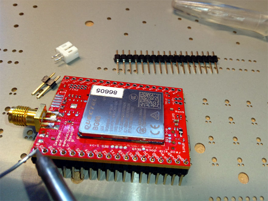 image 01 - xyz-mIoT pin soldering image 01 - xyz-mIoT pin soldering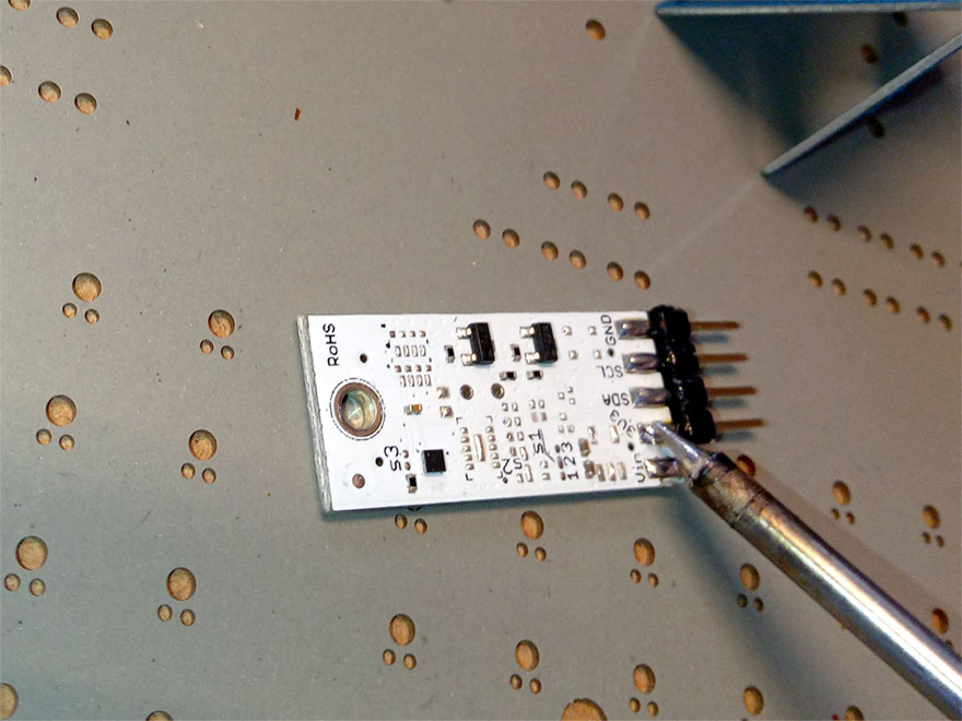 image 02 - HDC2010 sensor pin soldering image 02 - HDC2010 sensor pin soldering
b. Solder the battery connectors. Identify the battery (marked as "LiPO") soldering pads on the PCB. First, solder the 2PIN header in the same direction as you've soldered the previous headers(image 03). Then solder horizontally (in the edge of the PCB) to the same "LiPO" pads, the JST connector (image 04). Watch the polarity for the JST connector!!!
Follow the templates in images bellow.
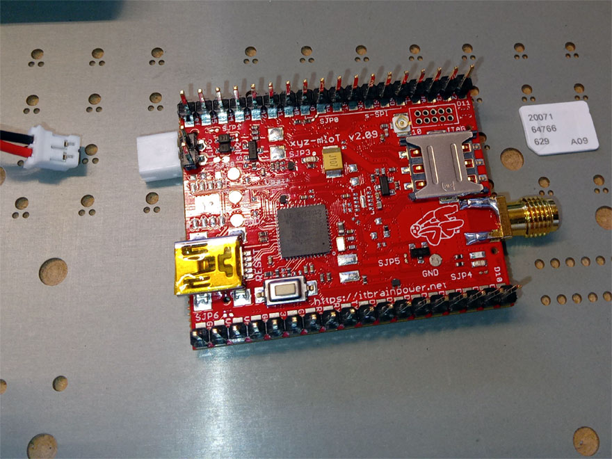 image 03 - battery 2 PIN header detail image 03 - battery 2 PIN header detail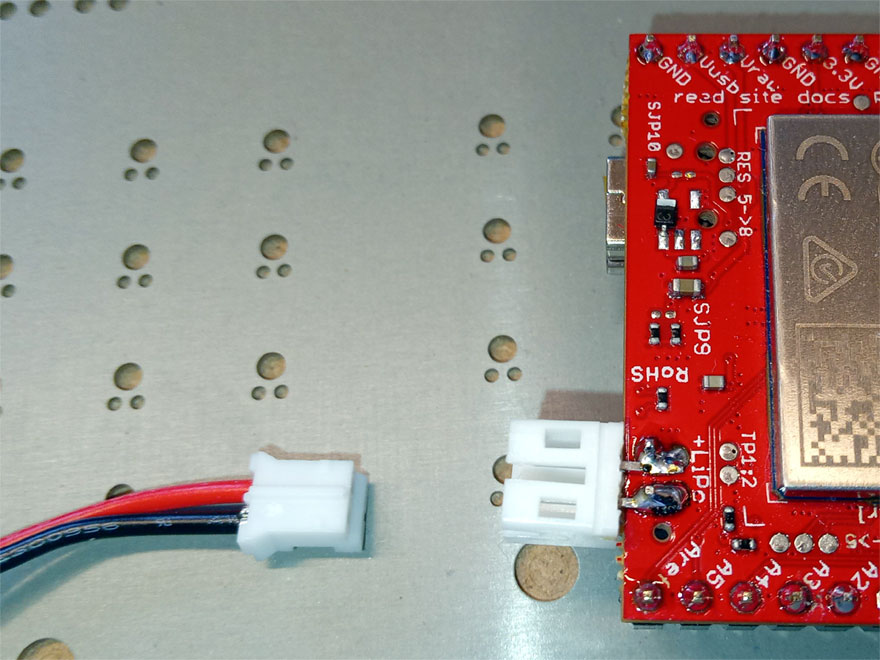 image 04 - battery JST connector detail image 04 - battery JST connector detail
c. You're almost there! Do not forget to check the solderings for any short circuits and for "cold" solderings!!
Now, your xyz-mIoT shield should look in image bellow.
 image 05 - low power kit with headers and connectors soldered image 05 - low power kit with headers and connectors soldered
STEP 2 - powering and debuging reference
Step 2.1 - Powering the development kit
Relevant info about xyz-mIoT BG96 ULP [SKU: ITBP-4083] including powering info can be found here.
Same, for xyz-mIoT BG95-M2 ULP [SKU: ITBP-4081] or xyz-mIoT BG95-M3 ULP [SKU: ITBP-4095] here.
In following labs, we will power the xyz-mIoT BG96 ULP version from Lithium primer batteries [nominal 3.6V, > 2100mAh and min. 50mA sustained current @ 25C] - bellow image 06, or from 3.3V source provided from the USB-serial adapter [CP2102] - bellow image 07.
 image 06 - powering from battery. Insert the battery connector into the JST connector. image 06 - powering from battery. Insert the battery connector into the JST connector.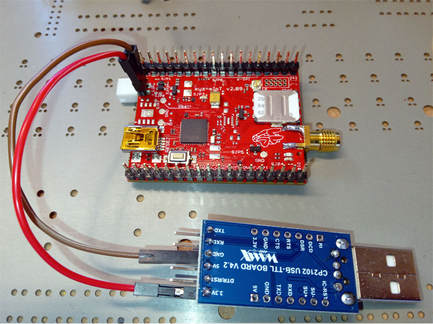 image 07 - powering from 3.3V provided by CP2102 USB-serial image 07 - powering from 3.3V provided by CP2102 USB-serial
adapter. Use the 3.3V pin!!!
VERY IMPORTANT:
a. the maximum admisible powering voltage is 3.70V. This means that this board should be powered only from lithium primer* batteries or from 3.3V power supplies.
b. DO NOT SHORT-CIRCUIT the power supply or battery leeds/wires!
c. DO NOT REVERSE THE POLARITY when connecting the power supply or the battery to the xyz-mIoT BG96 ULP!
d. DO NOT MIX the power sources! Use as powering source OR 3.3V from the USB-serial adapter OR the battery!
* in our tests, we've used EVE ER14505 lithium primer batteries having wires and JST connector connected.
Step 2.2 - low power kit USB, serial ports, debuging and programming references
About ports, programming and RUN modes, bref info
-
in addition to hardware Serial0 port (dedicated for modem communication) and Serial1 port (available on RX0 and TX1 pads), the xyz-mIoT boards have two Serial ports implemented via board USB-serial Arduino driver.
-
the first USB Serial* can be used in RUN, but NOT ultra low power enabled, for normal mode debug and data exchange with your PC. The first USB Serial it's NOT available in ultra low power mode.
-
the second USB Serial it's dedicated for programming and it's available in programming mode only.
-
in RUN the normal mode or ultra low power mode will be activated accordingly to the loaded software (software that is or not low power).
-
the programming mode** can be enabled by fast double press of the RESET switch. The normal mode in RUN should be available after programming MCU reboot or after press once the RESET switch.
-
the board programming should be done with the USB cable connected and with programming mode enabled.
-
always unplug the USB cable from the xyz-mIoT board or from your PC when RUN ultra low power programs (required to preserve the low power consumption).
-
ultra low power debug is done via Serial1[RX0 and TX1] connected to PC via the CP2102 UART-USB adapter.
.
* the first USB Serial it's available under Arduino environment as USBSerial name.
** in programming mode the SYSTEM LED[yellow / D13 LED] should have fluctuating luminosity.
Bellow, wiring for ultra low power debug when powering source is the USB-serial adapter (image 08) or came from battery image 09.
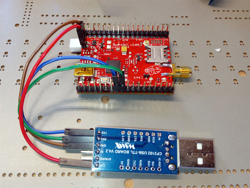 image 08 - ULP mode debug wiring (power came from 3.3V USB-Serial adapter). The power wiring it's present. image 08 - ULP mode debug wiring (power came from 3.3V USB-Serial adapter). The power wiring it's present.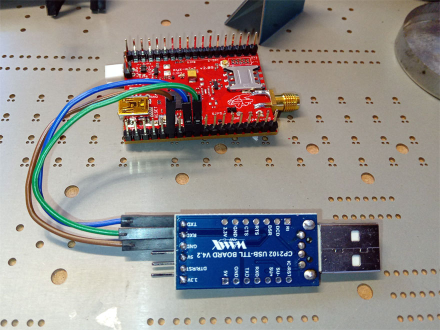 image 09 - ULP mode debug wiring (power came from battery). image 09 - ULP mode debug wiring (power came from battery).
Battery wiring not shown.
STEP 3 - software, drivers and more
Software versions bref info
-
all drivers and directives here refers to Microsoft Windows 10 [x86] usage
-
certaign drivers may request "Win10 non signed drivers" installing. Do not re-invent the wheel, just google for.
-
downloading packages from our site may request your email address, the product IMEI and/or product SKU. The IMEI's writen on the modem and inside the product box. The product SKU it's writen on the box label.
-
Arduino v. 1.8.5 it's requiered.
-
just in case... we use Tera Term terminal, 7 ZIP for archive decompression and Notepad++ for libraries editing.
Software and drivers install
-
If you do not have installed Arduino v. 1.8.5 you should install it. You may download it from https://www.arduino.cc/en/software or from https://itbrainpower.net/downloads.
Install it as distinct instance.
-
Download "LTE CATM / NB-IoT development kit bundle" from https://itbrainpower.net/downloads.
-
Expand the "ltecatm-nbiot-bundle" archive. You should notice some folders including xyz-Arduino_hardware_class, xyz-mIoT_RTCC_WDT_Arduino_classes, xyz-mIoT_LOW_POWER_Arduino_classe, sensors and drivers.
-
Install the "drivers". Keep in mind "Win10 non signed drivers" notice up-here.
-
Install the xyz-Arduino_hardware_class. Open the Arduino environment.
1. In Arduino select "Tools\Board" then select "Boards manager". Install "Arduino SAMD Boards (32-bits ARM CORTEX-M0) by Arduino version 1.6.17"
2. Finish instalation, then restart Arduino.
3. Select "File\Preferences". In "Settings" tab, find "schetchbook location data" and copy the path (let's name it "path_to_Arduino").
4. Close Arduino.
5. Explore the path copied before and expand "hardware" the folder. Make a backup copy of the "samd" folder.
6. Replace the "samd" folder with the one expanded from "xyz-mIoT_Arduino_hardware_class.zip".
7. Restart Arduino. In "Tools\Board" listing, at bottom of boards enumaration, you will find the "itbrainpower.net xyz-mIoT" board.
Alternative, in order to preserve your "samd" folder:
- just copy necesary xyz-mIoT files in "variants", "drivers" and "bootloaders\zero" folders.
- edit, as necessary, the "boards.txt"
-
Install the xyz-mIoT_RTCC_WDT_Arduino_classes.
1. Expand the archive. Take a look at readme files.
2. Copy the RTCZero and WDTZero Arduino Libraries folders into the Arduino Library folder.
3. Restart Arduino.
-
Install the xyz-mIoT_LOW_POWER_Arduino_class.
1. Expand the archive. Take a look at readme files.
2. Copy the xyz-mIoT low power Arduino folder into the Arduino Library folder.
3. Restart Arduino.
-
Install sensors classes (do this for both HDC2010 and BME688 sensors).
1. Expand the archive. Take a look at readme files.
2. Copy the s-Sense-HDC2010 / s-Sense-BME68x class into the Arduino Library folder.
3. Restart Arduino.
|


