itbrainpower.net
|
|||||||||||||||||||||||||||||||||||||||||||||||||||||||||||||||||||||||
CCS811 + HDC2010 breakout :: FEATURES 
|
|||||||||||||||||||||||||||||||||||||||||||||||||||||||||||||||||||||||
CCS811 + HDC2010 breakout :: INTERFACES, PADS and SOLDER JUMPERS
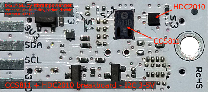
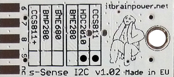
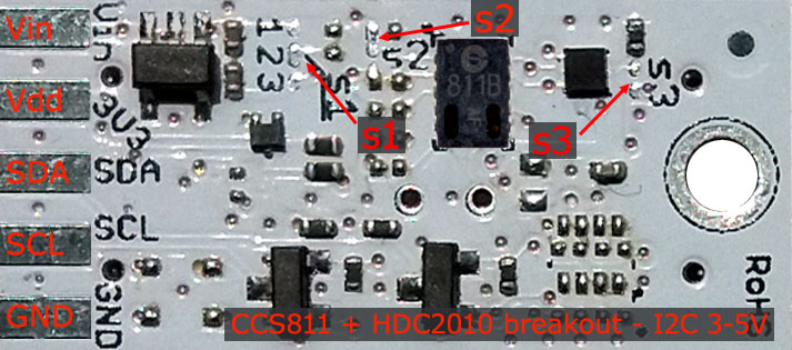
I2C and POWERING INTERFACEIn the left edge of the top PCB side, top to bottom:1. Vin - POWER IN 3.3V / 5V (default) * 2. 3V3 - Vdd - LDO output (default) / LDO bypass IN ** 3. SDA - I2C SDA [default, pulled up at Vin]*** 4. SCL - I2C SCL [default, pullup up at Vin]*** 5. GND - POWER and I2C GROUND * Default, the I2C reference voltage follow the Vin voltage. If your board (Arduino/other) it's 5V compliant, connect +5V to Vin. Similar, for 3.3V compliant board(RPI/Arduino)connect 3.3V source to Vin. ** 3.3V voltage it's available on Vdd PAD, if Vin it's connected to 5V. Bypass LDO - see schema and read docs. *** Default, the I2C reference voltage follows the Vin voltage! Read bellow about I2C reference voltage and s1 solder jumper. SOLDER JUMPERSs1 : I2C reference [Vin or 3V3-bypass], default Vin *s2 : CCS811 I2C address [0x5A/0x5B], default 0x5A * s3 : HDC2010 I2C address [0x40/0x41], default 0x40 * * Read about s1, s2 and s3 functionality bellow. SIGNALS INTERFACE and MARKINGIn the left edge of the bottom PCB side, top to bottom:6. CCS811 WAKE* input (active LOW) 7. CCS811 RESET* input (active LOW) 8. CCS811 INTERRUPT* output (w. pullup***) 9. HDC2010 INTERRUPT** output (w. pullup***) nc. NOT CONNECTED * In order to wake the CCS811 sensor, the WAKE signal must be shifted and kept at LOW level (connect directly to GND or controlled via MCU digital port). * Read about CCS811 WAKE, RESET and INTERRUPTS in CCS811 documentation! ** Read about HDC2010 INTERRUPTS in HDC2010 documentation! * & ** Taking a look at how-to posts and inside software examples may be quite helpful. *** Default HIGH. Observe the sensor breakout marking on PCB board (here, CCS811 and HDC2010 sensors are marked as populated). |
|||||||||||||||||||||||||||||||||||||||||||||||||||||||||||||||||||||||
| | |||||||||||||||||||||||||||||||||||||||||||||||||||||||||||||||||||||||
CCS811 + HDC2010 breakout :: Arduino / Raspberry PI basic interfacing |
|||||||||||||||||||||||||||||||||||||||||||||||||||||||||||||||||||||||
|
|||||||||||||||||||||||||||||||||||||||||||||||||||||||||||||||||||||||
CCS811 + HDC2010 breakout :: solder jumpers description; power scenarioss1* - I2C reference voltage selector - shipped with circuit 1-2 closed and circuit 2-3 open (default mode). In default mode, the I2C reference voltage follows the voltage applied to Vin! Default mode use cases: - shield/MCU it's 5V compatible ==> connect Vin at 5V; the I2C reference it's 5V! - SBC/shield/MCU it's 3.3V compatible ==>connect Vin at 3.3V; the I2C reference it's 3.3V!. Alternate mode - I2C reference voltage follows the Vdd voltage! - modify s1 as: 1-2 circuit open, 2-3 circuit closed [carefully interrupt/cut the circuit line between pads 1 and 2, and solder over pads 2 and 3]. Alternate mode scenarios: - apply 3.6-7V to Vin. The I2C reference voltage it's set at 3.3V! Also, at Vdd pad (LDO output) 3.3V (up to 100mA) it's available for third part powering (anyway, try to keep the sunk current as low as possible, in order to avoid thermal errors). - keep Vin not connected. Apply 2.8 or 3.3V to Vdd (the LDO it's bypassed). The I2C reference voltage it's set at voltage applied to Vdd pad! s2 - CCS811 I2C address - default circuit open, CCS811 having 0x5A as I2C address. Solder over s2 pads [circuit closed] in order to select the alternate I2C address [0x5B]. s3 - HDC2010 I2C address - default circuit open, HDC2010 having 0x40 as I2C address. Solder over s3 pads [circuit closed] in order to select the alternate I2C address [0x41]. * Consult s-Sense block schema for more information. See projects/how to section. |
|||||||||||||||||||||||||||||||||||||||||||||||||||||||||||||||||||||||
CCS811 + HDC2010 breakout :: ARDUINO & RaspberryPI software
s-Sense air quality and environmental sensors examples for Arduino and RaspberryPI may be downloaded from our download page. CCS811 + HDC2010 breakout :: DOCUMENTATION DOWNLOAD/ONLINEThe s-Sense environmental sensors documentation can be found here. CCS811 + HDC2010 breakout :: ARDUINO & RaspberryPI projectsArduino & RaspberryPI projects based on itbrainpower.net products |
|||||||||||||||||||||||||||||||||||||||||||||||||||||||||||||||||||||||
CCS811 + HDC2010 breakout :: ORDER ONLINEOrder online s-Sense air quality and environmental sensor breakout boards | |||||||||||||||||||||||||||||||||||||||||||||||||||||||||||||||||||||||
CCS811 + HDC2010 breakout :: ORDER FROM OUR DISTRIBUTORSChoose and order from one distributor near you. View/save pdf version of this page. | |||||||||||||||||||||||||||||||||||||||||||||||||||||||||||||||||||||||
the alphabet : order online a-gsmII shield [new] b-gsmgnss shield [new] a-gsm shield c-uGSM shield (micro) d-u3G shield (micro) f-audioOutputs adapter g-SPS boards i-hatGSM3G adapter j-328GSM3GLader adapter h-nanoGSM shield (nano) l-LTE shield s-Sense sensor breakout boards [HOT] u-GSM shield - CAT M1 / NB IoT / LTE [newest] xyz-mIoT integrated sensors IOT shield [newest] IoT product of week featured product [STRATUM1 NTP server] DOWNLOADS FAQs |
|||||||||||||||||||||||||||||||||||||||||||||||||||||||||||||||||||||||
|
Security, automation, monitoring, IoT and special purpose equipments: STRATUM 1 NTP server GNSS syncronized SMS gateway with parallel processing Temp., hum. and more monitor w. SMS alarm Development kits: LTE CATM + NB IoT development kit(s) Arduino and Raspberry PI how-to and tutorials hottest project newest project newest hardware how to newest software tutorial view all tutorials BME688 Arduino how to CCS811 Arduino how to HDC2010 Arduino how to BME680 Arduino how to BME280 Arduino how to BMP280 Arduino how to CCS811 RPI how to HDC2010 RPI how to BME680 RPI how to BME280 RPI how to BMP280 RPI how to Covid19 related resources: ZOOM speaker (w. Arduino shield and a-gsmII) - covid19 response help for elderly peoples PARP purified air flow controller for 12VDC blowers powered from 5V LiION power bank temperature, humidity and pressure sensor temperature and pressure sensor BME280 Arduino how to BMP280 Arduino how to BME280 RPI how to BMP280 RPI how to our environmental and air quality sensor breakouts: OPT3002 BME688 CCS811 + HDC2010 combo BME680 CCS811 BME280 BMP280 HDC2010 |
|||||||||||||||||||||||||||||||||||||||||||||||||||||||||||||||||||||||
|
distributors
contact
privacy policy
terms and conditions |
|||||||||||||||||||||||||||||||||||||||||||||||||||||||||||||||||||||||
| document version 0.9162 / 2020-08-07 | © R&D Software Solutions srl | ||||||||||||||||||||||||||||||||||||||||||||||||||||||||||||||||||||||
