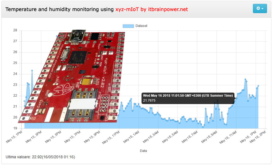
About project
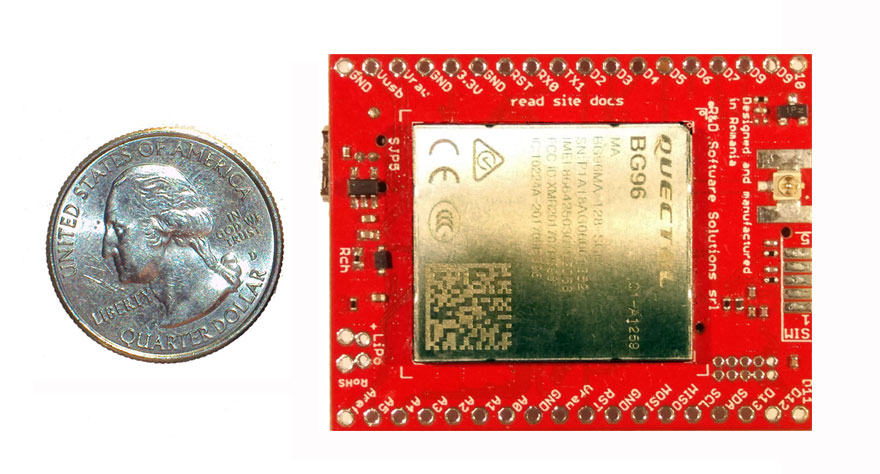
At April 08th 2018, R&D Software Solutions srl [itbrainpower.net] revealed to the public the announcement of the xyz-mIoT by itbrainpower.net shield - the first, and the most compact, IoT board that combines the versatility of ARM0 micro-controller (Microchip/Atmel ATSAMD21G in Arduino Zero compatible design), the comfortable use of the embedded sensors bundle with conectivity provided by LPWR LTE CAT M1 or NB-IoT long-range & low-power modems or legacy 3G / GSM modems.
The xyz-mIoT shield may have up to 5 integrated sensors, as: THS (temperature and humidity sensors) - HDC2010, tVOC & eCO2 (air quality sensor - CO2 total volatile organic compounds- CO2 equivalent) - CCS811 , HALL (magnetic sensor) - DRV5032 sau or IR (infrared sensor) KP-2012P3C , secondary IR (infrared sensor) - KP-2012P3C , TILT (movement vibration sensor) or REED (magnetic sensor) - SW200D.
In order to highlight rich features offered thanks to R&D Software Solutions srl advanced design due to highly sensors integration, please refer to brief comparative chart. Embedded sensors that populates the xyz-mIoT shield are dependent on PN ordered (check here for available PN).
xyz-mIoT shield brief tech references:
xyz-mIoT shield block schematics
xyz-mIoT shield pinout, port mapping and LEDs
Required time: 10-15 minutes.
The implementation time may vary depending on previous user experience. Arduino environment installing and manual Arduino class installing are not covered by this how to; try google it. Support libraries and the source code used in this how to are available for download, for registered users, here.
Difficulty: beginner - intermediate.
Bill of materials
- xyz-mIoT shield having integrated HDC2010 sensor, as following PN:
XYZMIOT209#BG96-UFL-1100000 [LTE CAT M1 and GSM modem],
or
XYZMIOT209#M95FA-UFL-1100000 [GSM only modem] - nano-size [4FF] LTE CATM1 or 2G SIM card [having data plan enabled]
- small LiPo battery
- GSM embedded antenna with uFL [check xyz-mIoT accesories] or,
- GSM antenna with SMA plus u.FL to SMA pigtail [check xyz-mIoT accesories]
Step1 [hardware, soldering]:
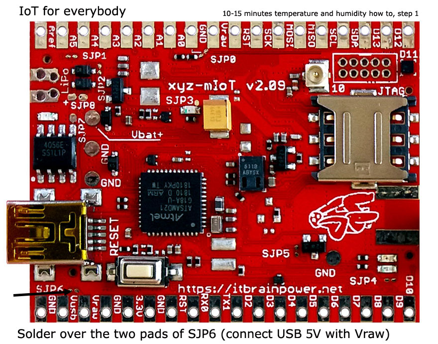
Enable 5V from USB to be as primary power supply for the board as described up here. Alternative: solder both connectors rows, place the board into one breadboard and connect between Vusb and Vraw using one male-male breadboard wire.Solder the LiPo connector. Keep in mind the LiPO polarity!
DOUBLE CHECK YOUR SOLDERINGS!!!.
Step2[hardware, bring all together]:
Insert the micro-SIM in his slot [the SIM must have the PIN check procedure removed]. Connect the antenna, then connect the USB cable to xyz-mIoT USB port and to your computer. Connect the LiPo battery.
Step 3 [software download and install, preliminary settings]
a. Download and install "xyz-mIoT shields Arduino class", then download the last version of classes: "IoT REST [transparent socket] support for xyz-mIoT shields" and "xyz-mIoT shields SENSORS support Arduino class" from here.
b. Install the classes. Uncompress the archives and install the classes - in a nutshell:
- copy the "xyz-mIoT shields Arduino class" files in Arduino local hardware folder (mine is: "C:\Users\dragos\Documents\Arduino\hardware"), then
- copy the the support classes folders into your Arduino local user folder [mine is: "C:\Users\dragos\Documents\Arduino\libraries"] and
- restart Arduino environment.
More detail about manual library installing, read Arduino library manual installation.
c. Make a folder named "xyz_mIoT_v41_temp_humidity".
d. Copy the code bellow, paste it one new file and save the file as "xyz_mIoT_v41_temp_humidity.ino" in the folder created in previous step. Alternate, you can
download from here (right click & save as):
LTE CATM1 or GSM temperature and humidity IOT CLOUD monitoring using xyz-mIoT - Arduino main code
xyz_mIoT_v41_temp_humidity.ino
| 1 | /* |
| 2 | xyz_mIoT_Robofun_cloud_REST_demo.ino v 0.41b/20181005 - SOFTWARE EXAMPLE |
| 3 | COPYRIGHT (c) 2015-2018 Dragos Iosub / R&D Software Solutions srl |
| 4 | |
| 5 | You are legaly entitled to use this SOFTWARE ONLY IN CONJUNCTION WITH xyz-mIoT by itbrainpower.net DEVICES USAGE. Modifications, derivates and |
| 6 | redistribution of this software must include unmodified this COPYRIGHT NOTICE. You can redistribute this SOFTWARE and/or modify it under the terms |
| 7 | of this COPYRIGHT NOTICE. Any other usage may be permited only after written notice of Dragos Iosub / R&D Software Solutions srl. |
| 8 | |
| 9 | This SOFTWARE is distributed is provide "AS IS" in the hope that it will be useful, but WITHOUT ANY WARRANTY; without even the implied |
| 10 | warranty of MERCHANTABILITY or FITNESS FOR A PARTICULAR PURPOSE. |
| 11 | |
| 12 | Dragos Iosub, Bucharest 2018. |
| 13 | https://itbrainpower.net |
| 14 | */ |
| 15 | /*This demo is written for xyz-mIoT boards. How to: https://itbrainpower.net/a-gsm/LTE-CATM1-GSM-temperature-humidity-integrated-sensors-IOT-CLOUD-monitoring-xyzmIOT_howto */ |
| 16 | /*IMPORTANT NOTICE 1: check in itbpGSMdefinition.h, line 51 set __itbpModem__ xyzmIoT and choose __Qmodule__ from lines 53-54*/ |
| 17 | /*IMPORTANT NOTICE 2: in "itbpGPRSIPdefinition.h" set the APN, LOGIN and PASSWORD values using the APN value of your GSM provider*/ |
| 18 | /*IMPORTANT NOTICE 3: in "itbpGPRSIPdefinition.h" set the SERVER_ADDRESS and the SERVER_PORT for CLOUD Robofun*/ |
| 19 | /*IMPORTANT NOTICE 4: for BG96 variants --> CATM1/GSM configuration mode and priority search ...see function call at lines 252->260*/ |
| 20 | /*IMPORTANT NOTICE 5: temperature and humidity data available only for variants having HDC2010 sensor embedded (PN sufix file: 1xxxxxx); |
| 21 | variants w/o HDC2010 sensor embedded - dummy values are generated... you may like to implement something with rand() function?*/ |
| 22 | |
| 23 | /*REST cloud specific, more parameters in itbpGPRSIPdefinition.h*/ |
| 24 | #define cloudURL "http://iot.robofun.ro/api/v1/senzor/" |
| 25 | #define sensorValURL "/input?value=" |
| 26 | #define tempTocken "74g0rvibt3cskrpb5457r4jv45" //replace with your temperature sensor tocken |
| 27 | #define humiTocken "mp86hppb262b832df1vecrsg5g" //replace with your humidity sensor tocken |
| 28 | |
| 29 | int samplingPeriod = 60; //interval in seconds between scans... keep it > 60 sec |
| 30 | |
| 31 | /*local vars, sensors and actuators exchanged with the cloud*/ |
| 32 | //char dttime [31]; |
| 33 | char IMEI [16]; |
| 34 | double temperature = 0; |
| 35 | double humidity = 0; |
| 36 | /*local vars, sensors and actuators exchanged with the cloud*/ |
| 37 | |
| 38 | |
| 39 | #include <itbpGSMClass_v0_6.h> |
| 40 | |
| 41 | #define DEBUG(x) {__itbpDebugPort__.print(millis());__itbpDebugPort__.print(" - ");__itbpDebugPort__.println(x);} |
| 42 | #define DEBUGP(x,y) {__itbpDebugPort__.print(millis());__itbpDebugPort__.print(" - ");__itbpDebugPort__.print(x);__itbpDebugPort__.println(y);} |
| 43 | |
| 44 | //#if (__itbpModem__ != xyzmIoT) |
| 45 | #ifndef _VARIANT_ARDUINO_ZERO_ //update v0.6 [Arduino ZERO and modemless xyz-mIoT boards was included] |
| 46 | int freeRam () { |
| 47 | extern int __heap_start, *__brkval; |
| 48 | int v; |
| 49 | return (int) &v - (__brkval == 0 ? (int) &__heap_start : (int) __brkval); |
| 50 | } |
| 51 | #endif |
| 52 | |
| 53 | // initialize the library instance |
| 54 | aGsmClient client; |
| 55 | |
| 56 | |
| 57 | /* sensor side here */ |
| 58 | #include <HDC2010.h> //I2C THS HDC2010 from Texas [option for xyz-mIoT] |
| 59 | /*following definitions [used in software] are placed in xyz-mIoT variant.h |
| 60 | HDC2010 related: |
| 61 | - I2C_HDC2010_ADDRESS 0x40 //default HDC2010 I2C address |
| 62 | - HDC2010_INTERRUPT_PIN 5 //pin mapped as IRQ for HDC2010. Confort zone example. Read HDC2010 documentation for more. |
| 63 | |
| 64 | HALL related: |
| 65 | - HALL_IRQ_PIN 6 //IRQ used for HALL. Or read this pin value for pulling mode. |
| 66 | - HALL_PULLUP_PIN 25 //pullup this pin in order to enable HALL sensor readings. |
| 67 | |
| 68 | Voltage measurments: |
| 69 | - VbatPin A5 |
| 70 | - VrawPin A4 |
| 71 | |
| 72 | Modem control assigned digital pis: |
| 73 | - CTRL_PIN_MODEMPOWER 38 //Digital pin used enable/disable modem power |
| 74 | - lprCtrlPIN 26 //Digital pin used to control the modem on/off |
| 75 | - CTRL_PIN_GNSSANTENNAPOWER 4 //Digital pin used to control the active GNSS antenna power |
| 76 | */ |
| 77 | HDC2010 sensor(I2C_HDC2010_ADDRESS); |
| 78 | /* sensor side here */ |
| 79 | |
| 80 | |
| 81 | unsigned long startTime = 0; |
| 82 | |
| 83 | bool ledState = 0; |
| 84 | |
| 85 | |
| 86 | /* |
| 87 | Function to parse the server responce |
| 88 | Vars: |
| 89 | Type ==> GETACTUATOR / POSTSENSOR |
| 90 | value ==> int [send this value for SENSOR, update this for ACTUATOR] |
| 91 | timeout ==> int, timeout in seconds to wait for and parse the server responce |
| 92 | Returns: |
| 93 | 1 on success |
| 94 | 0 on error [found closed socket or PDP deactivation] |
| 95 | -1 on server timeout |
| 96 | */ |
| 97 | int readServerResponse(int timeout){ |
| 98 | |
| 99 | unsigned long startTime; |
| 100 | int ret =0; |
| 101 | startTime = millis(); |
| 102 | delay(10); |
| 103 | __itbpDebugPort__.println(F("start read...")); |
| 104 | while(true){ |
| 105 | client.readline(1000); |
| 106 | __itbpDebugPort__.println(client.resp);//just to see the server response |
| 107 | if (strstr(client.resp, "1;")) |
| 108 | { |
| 109 | __itbpDebugPort__.println(F("found confirmation...")); |
| 110 | ret = 1; |
| 111 | } |
| 112 | |
| 113 | if (strstr(client.resp, "0;")) |
| 114 | { |
| 115 | __itbpDebugPort__.println(F("error returned...")); |
| 116 | ret = -1; |
| 117 | } |
| 118 | |
| 119 | if (strstr(client.resp, sockDisconnected0)||strstr(client.resp, sockDisconnected1)||strstr(client.resp, sockDisconnected2)) |
| 120 | { |
| 121 | __itbpDebugPort__.println(F("sk disconnected...")); |
| 122 | client.stop(); //4 LTE and 3G |
| 123 | return ret; |
| 124 | }//sockDisconnected0 |
| 125 | |
| 126 | if(millis() - startTime > (unsigned long)timeout*1000 ) |
| 127 | { |
| 128 | __itbpDebugPort__.println(F("mark to...")); |
| 129 | client.stop(); //need to clean DATA interface and return the to AT command interface |
| 130 | return -2; |
| 131 | } |
| 132 | } |
| 133 | return -3;//never here |
| 134 | } |
| 135 | |
| 136 | |
| 137 | |
| 138 | |
| 139 | void sendGetRequest(char * sensorTocken, double sensorData){ |
| 140 | String data; |
| 141 | //data = String(cloudURL) + String(sensorTocken) + String(sensorValURL) + String(humidity, DEC); |
| 142 | data = String(cloudURL) + String(sensorTocken) + String(sensorValURL) + String(sensorData); |
| 143 | __itbpDebugPort__.println(data); |
| 144 | |
| 145 | client.print("GET "); |
| 146 | client.print(data); |
| 147 | client.println(" HTTP/1.1"); |
| 148 | client.println(F("Host: " SERVER_ADDRESS)); |
| 149 | client.println(F("Connection: close")); |
| 150 | client.println(); |
| 151 | } |
| 152 | |
| 153 | |
| 154 | |
| 155 | void sendData( void){ |
| 156 | //send temperture data |
| 157 | if (client.connected() || client.connect()){ |
| 158 | |
| 159 | sendGetRequest(tempTocken, temperature); |
| 160 | |
| 161 | readServerResponse(SERVER_REPLY_TIMEOUT); |
| 162 | }else{ |
| 163 | __itbpDebugPort__.println(F("Socket/GPRS error...")); |
| 164 | } |
| 165 | //send humidity data |
| 166 | if (client.connected() || client.connect()){ |
| 167 | //client.print(demoData); |
| 168 | sendGetRequest(humiTocken, humidity); |
| 169 | //client.println("\r\n"); |
| 170 | readServerResponse(SERVER_REPLY_TIMEOUT); |
| 171 | }else{ |
| 172 | __itbpDebugPort__.println(F("Socket/GPRS error...")); |
| 173 | } |
| 174 | } |
| 175 | |
| 176 | |
| 177 | void setup(){ |
| 178 | //#if (__itbpModem__ == xyzmIoT) |
| 179 | #ifndef _VARIANT_ARDUINO_ZERO_ //update v0.6 [Arduino ZERO and modemless xyz-mIoT boards was included] |
| 180 | delay(10000); |
| 181 | |
| 182 | /* |
| 183 | pinMode(HALL_PULLUP_PIN, OUTPUT); |
| 184 | digitalWrite(HALL_PULLUP_PIN, HIGH); // power the HALL sensor |
| 185 | */ |
| 186 | |
| 187 | #endif |
| 188 | |
| 189 | __itbpDebugPort__.begin(115200); //start debug port connection |
| 190 | //configure led |
| 191 | pinMode(LED_BUILTIN, OUTPUT); //embedded LED status indicator |
| 192 | digitalWrite(LED_BUILTIN, LOW); |
| 193 | ledState = 0; |
| 194 | |
| 195 | /*sensor side*/ |
| 196 | sensor.begin(); //I2C THS sensor init |
| 197 | sensor.reset(); //reset H2010 |
| 198 | |
| 199 | //sensor.setTemperatureOffset(0b11000000); //-10.32 |
| 200 | sensor.setTemperatureOffset(0b11010111); //-6.64 |
| 201 | |
| 202 | // Set up the comfort zone |
| 203 | sensor.setHighTemp(28); // High temperature of 28C |
| 204 | sensor.setLowTemp(22); // Low temperature of 22C |
| 205 | sensor.setHighHumidity(55); // High humidity of 55% |
| 206 | sensor.setLowHumidity(40); // Low humidity of 40% |
| 207 | |
| 208 | // Configure interrupt pin |
| 209 | /*sensor.enableInterrupt(); // Enable the Interrupt/DRDY pin |
| 210 | sensor.enableThresholdInterrupt(); // Enable Interrupt triggering based on comfort zone |
| 211 | sensor.setInterruptPolarity(ACTIVE_HIGH); // Set Interrupt pin to Active High |
| 212 | sensor.setInterruptMode(COMPARATOR_MODE); // Set Interrupt to return to inactive state when in bounds |
| 213 | */ |
| 214 | // Configure Measurements |
| 215 | sensor.setMeasurementMode(TEMP_AND_HUMID); // Set measurements to temperature and humidity |
| 216 | //sensor.setRate(ONE_HZ); // Set measurement frequency to 1 Hz |
| 217 | sensor.setRate(MANUAL); // Set measurement frequency to 1 Hz |
| 218 | sensor.setTempRes(FOURTEEN_BIT); |
| 219 | sensor.setHumidRes(FOURTEEN_BIT); |
| 220 | |
| 221 | /* |
| 222 | // Configure Measurements |
| 223 | //sensor.setRate(ONE_HZ); // Set measurement frequency to 1 Hz |
| 224 | |
| 225 | // Configure THS Interrupt Pin |
| 226 | pinMode(HDC2010_INTERRUPT_PIN, INPUT); // HDC2010_INTERRUPT_PIN will be the interrupt input |
| 227 | attachInterrupt(digitalPinToInterrupt(HDC2010_INTERRUPT_PIN), alertTHS, CHANGE); //ISR "alertTHS" will be triggered by changes in ALERTTHSPIN |
| 228 | // Configure HALL Interrupt Pin |
| 229 | pinMode(HALL_IRQ_PIN, INPUT_PULLUP); // HALL_IRQ_PIN will be the interrupt input |
| 230 | attachInterrupt(digitalPinToInterrupt(HALL_IRQ_PIN), alertHALL, CHANGE); //ISR "alertHALL" will be triggered by changes in ALERTHALLPIN |
| 231 | |
| 232 | */ |
| 233 | //begin measuring |
| 234 | sensor.triggerMeasurement(); |
| 235 | temperature = /*100**/(double)sensor.readTemp(); |
| 236 | humidity = /*100**/(double)sensor.readHumidity(); |
| 237 | /*sensor side*/ |
| 238 | |
| 239 | |
| 240 | |
| 241 | //#if __itbpModem__ != xyzmIoT |
| 242 | #ifndef _VARIANT_ARDUINO_ZERO_ //update v0.6 [Arduino ZERO and modemless xyz-mIoT boards was included] |
| 243 | DEBUGP(F("Free RAM: "), freeRam()); |
| 244 | #endif |
| 245 | __itbpDebugPort__.println(F("...let's rock")); |
| 246 | __itbpDebugPort__.flush(); |
| 247 | |
| 248 | client.begin(); |
| 249 | |
| 250 | |
| 251 | #if __Qmodule__ == CATM1 // for BG96 modems |
| 252 | //Set bands, scan mode, scan sequence for BG96 only!!! Only just after client.begin()! |
| 253 | //client.setScanSequence(SCANSEQ_CATM1, SCANSEQ_GSM, SCANSEQ_NBIOT ); //left to right priority |
| 254 | client.setScanSequence(SCANSEQ_GSM, SCANSEQ_CATM1, SCANSEQ_NBIOT ); |
| 255 | |
| 256 | //client.setRegistrationMode(RegisterGSM); //GSM only registration mode allowed |
| 257 | //client.setRegistrationMode(RegisterCATM1); //CAT-M1 only registration mode allowed |
| 258 | client.setRegistrationMode(RegisterBOTH); //CAT-M1 or GSM registration mode allowed |
| 259 | |
| 260 | client.setBands(GSM_ALL, LTE_CATM1_ALL, LTE_NBIOT_ALL); //definitions in itbpGSMdefinition.h |
| 261 | #endif |
| 262 | |
| 263 | client.enableClockUpdate(1); //update available at next GSM boot |
| 264 | |
| 265 | client.getIMEI(); //IMEI value in client.resp |
| 266 | memset(IMEI,0x00, sizeof(IMEI)); |
| 267 | strcpy(IMEI,client.resp); |
| 268 | DEBUGP(F("IMEI: "), IMEI); |
| 269 | |
| 270 | client.attachGPRS(); |
| 271 | __itbpDebugPort__.println("connecting..."); |
| 272 | |
| 273 | |
| 274 | startTime = millis() + (unsigned long)samplingPeriod*1000;//force send on the spot |
| 275 | } |
| 276 | |
| 277 | |
| 278 | |
| 279 | |
| 280 | void loop(){ |
| 281 | if (millis() - startTime < (unsigned long)samplingPeriod*1000){//waiting period |
| 282 | //__itbpDebugPort__.println(F("...")); |
| 283 | //digitalWrite(25, LOW); |
| 284 | //digitalWrite(26, HIGH); |
| 285 | |
| 286 | ledState = ! ledState; |
| 287 | if(ledState != 0) |
| 288 | digitalWrite(LED_BUILTIN, HIGH); |
| 289 | else |
| 290 | digitalWrite(LED_BUILTIN, LOW); |
| 291 | delay(500); |
| 292 | |
| 293 | } |
| 294 | else{ |
| 295 | //digitalWrite(25, HIGH); |
| 296 | //digitalWrite(26, LOW); |
| 297 | |
| 298 | startTime = millis(); |
| 299 | digitalWrite(LED_BUILTIN, HIGH); //show sampling + uploadto cloud |
| 300 | |
| 301 | __itbpDebugPort__.println(F("")); |
| 302 | |
| 303 | |
| 304 | sensor.triggerMeasurement(); |
| 305 | delay(500); |
| 306 | temperature = /*100**/(double)sensor.readTemp(); |
| 307 | humidity = /*100**/(double)sensor.readHumidity(); |
| 308 | DEBUGP(F("Temp: "),temperature); |
| 309 | DEBUGP(F("Hum%: "),humidity); |
| 310 | /* |
| 311 | alarmHALL = digitalRead(ALERTHALLPIN); |
| 312 | DEBUGP(F("Hall: "),alarmHALL); |
| 313 | |
| 314 | if (client.connected()) client.transparentescape(); //switch to AT mode - not really neaded, but just to be sure |
| 315 | |
| 316 | client.getVoltage(); //Vbat value in client.resp |
| 317 | VBAT = atof(client.resp); |
| 318 | DEBUGP(F("Voltage: "),VBAT); |
| 319 | |
| 320 | client.getRTC(); //RTC value in client.resp |
| 321 | memset(dttime, 0x00, sizeof(dttime)); |
| 322 | strcpy(dttime,client.resp); |
| 323 | DEBUGP(F("Time: "),dttime); |
| 324 | */ |
| 325 | if (!client.connected()) client.transparent(); //switch to transparent socket mode, if available |
| 326 | |
| 327 | DEBUG(F("send sensors start")); |
| 328 | sendData(); //push sensors to the cloud |
| 329 | DEBUG(F("send sensors stop")); |
| 330 | |
| 331 | digitalWrite(LED_BUILTIN, LOW); //show sampling + uploadto cloud |
| 332 | ledState = 0; |
| 333 | } |
| 334 | |
| 335 | } |
| 336 | |
| 337 |
e. Make some settings in some files contained inside "IoT REST [transparent socket] support for xyz-mIoT shields" class:
- in "itbpGPRSIPdefinition.h" set the APN value, using the APN value of your GSM provider (Eg: NET for RO Orange)
- in "itbpGPRSIPdefinition.h" set the SERVER_ADDRESS and the SERVER_PORT for CLOUD Robofun
#define SERVER_ADDRESS "iot.robofun.ro"
#define SERVER_PORT "80"
- in "itbpGSMdefinition.h" comment default option for "__itbpModem__" and choose (delete comment sign) option
"#define __itbpModem__ xyzmIoT" (line 69)
- in "itbpGSMdefinition.h" choose the right modem for your xyz-mIoT flavour: for M95FA choose
"#define __Qmodem__ TWOG" (line 71)
or for BG96 choose
"#define __Qmodem__ CATM1" (line 70)
Step4 [Robofun cloud - define new sensors and copy TOKEN settings.]
Open https://iot.robofun.ro.
Create new account.
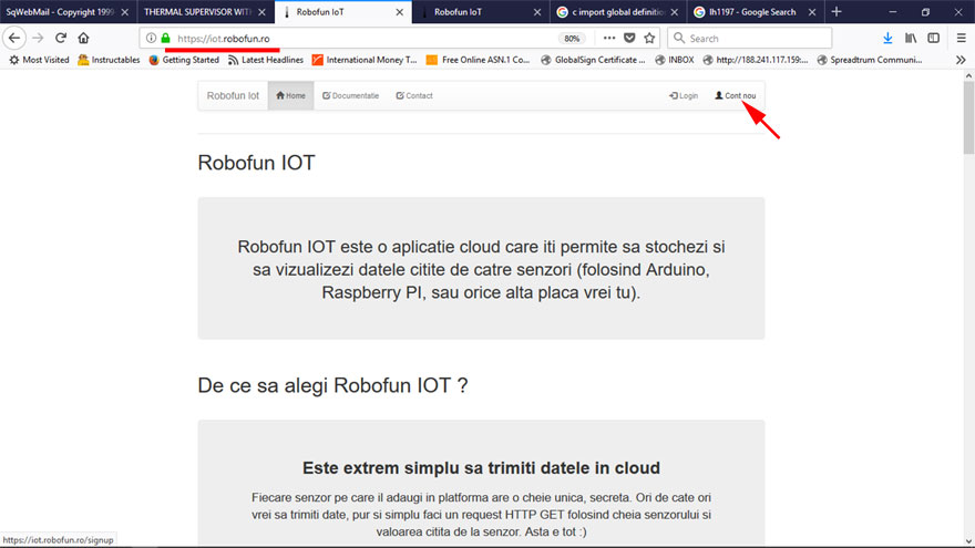
Add two new sensors (xyzmIOT_temperature and xyzmIOT_humidity).
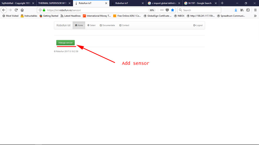
Scroll down the page until "TOKEN" chapter.
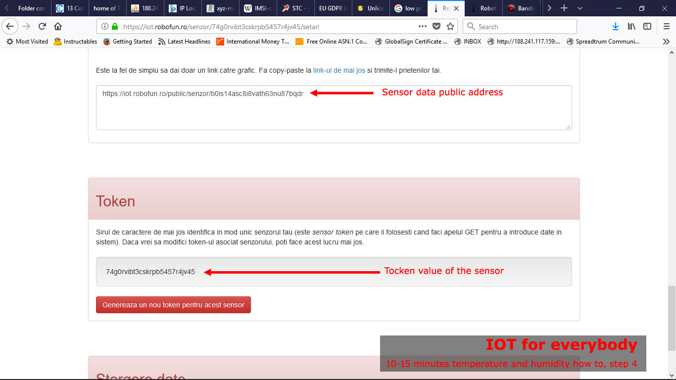
For each sensor, retain the "Tocken" id values. Those values will be used, next, to set sensors id[token id] in Arduino code.
In same page, a little bit above you will find the public Internet address where you will find the sensor data (observe marked in above picture).
Step5 [Arduino - sensors Tocken id, compile and upload IOT code]
Open in Arduino[(arduino.cc v >= 1.8.5] the xyz_mIoT_v41_temp_humidity.ino project.
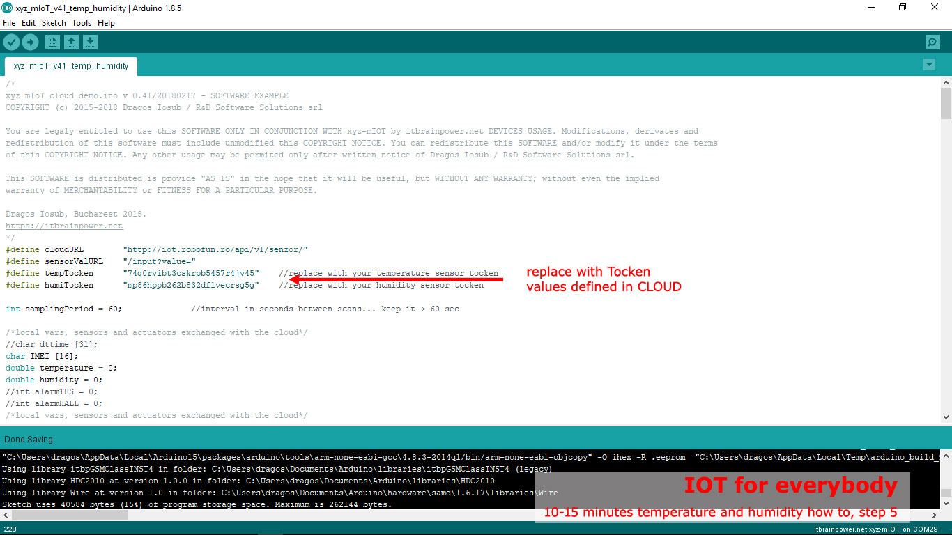 a. Set tempTocken and humiTocken values with the one retained in previous step [created in the CLOUD].
HINT: If you use xyz-mIoT shield equipped with Quectel BG96 module you may like to set the network scan sequence, set/restrict the LTE and GSM bands used or to select the network registration mode as "RegisterGSM", "RegisterBOTH" or as "RegisterCATM1" (to be able to access LTE CAT-M1 services the mobile network used and the SIM card must support LTE CATM1*) ...see functions calls at lines 252->260, right after client.begin() in function setup().
* we use for tests RO Orange LTE CATM1 enabled SIM.
b. Press twice (fast) the xyz-mIoT shield RESET button [the board will switch into programming mode].
 Select "itbrainpower.net xyz-mIoT" board and "itbrainpower.net xyz-mIoT" programming port in Arduino menu.
c. Compile and upload the code.
The xyz-mIoT shield will start to sample the temperature and humidity data (at 1min. rate) and to upload sampled values to the CLOUD.
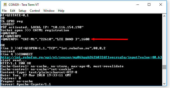 In order to visualize the debug output use the Arduino Serial Monitor or other terminal by selecting the debug port with following settings: 115200bps, 8N, 1.
The temperature logged data can be visualized in Robofun cloud sensor page or, in public (shared) page as we specified in Step4 .
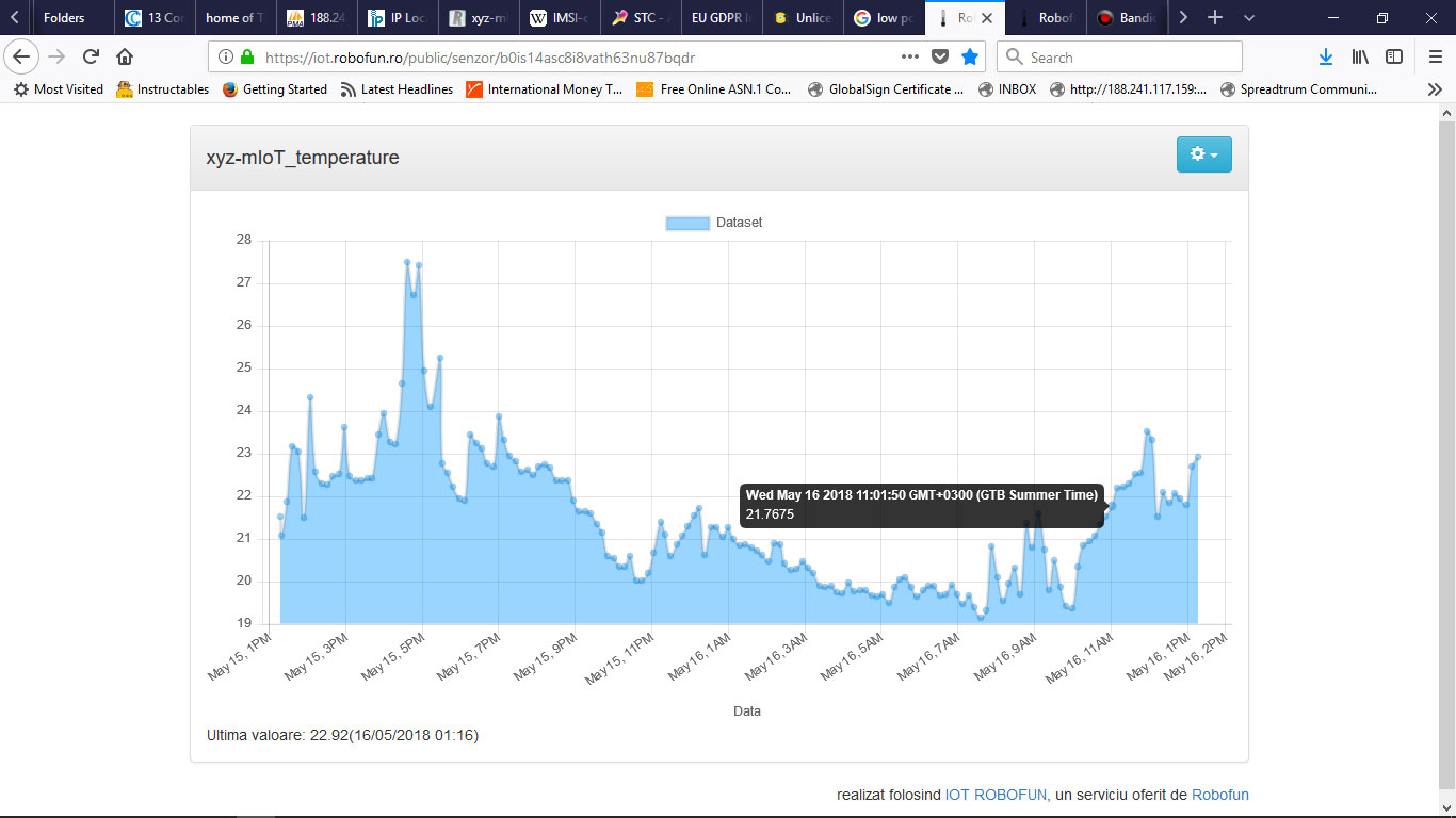
ENJOY!
TUTORIAL PROVIDED WITHOUT ANY WARRANTY!!! USE IT AT YOUR OWN RISK!!!!
