About this project
Our pal Valentin Chesaru (paul_vali82 at hot**il.com) send us following project built around the Ikea VINDRIKTNING PM2.5 sensor and the itbrainpower.net s-Sense BME688 / BME680 sensor(s).
This application uses the Ikea VINDRIKTNING housing and its USB-C supply connector. The modification is possible for ESPxxxx devices with Tasmota which includes the library for both embedded sensors.
A lot of additional documentation and video tutorials can be found on the internet - I suggest to be consulted especilly for information regarding Tasmota configuration. The configuration must be properly done from the Tasmota Web interface in order to be able to see the information from the sensors.
Main components included in this project
- Ikea VINDRIKTNING PM 2.5 sensor
- itbrainpower.net s-Sense BME688 AI sensor (PN: SS-BME688#I2C, SKU: ITBP-6007) more info, order
or,
- itbrainpower.net s-Sense BME680 VoC sensor (PN: SS-BME680#I2C, SKU: ITBP-6003) more info, order
- ESP8266 Wifi module
- USB to USB-C cable
- USB 5V supply, >1A capable (Ikea sensor asks for 2A in the manual, but this seems to be overrated)
Software preamble (ESP8266 tasmotaizing)
I recommend first to install the Tasmota firmware on the ESP8266, to avoid doing this with all the wires connected between the modules.
Step 1: Connect the ESP8266 to your PC and install the drivers for the USB to RS232 converter that is on the board. Most of them use the CH340 chip and Windows 10 doesn’t recognize it automatically, so you will have to install its driver from here.
Step 2: Download the Tasmota firmware writer Tasmotizer from github ) or use their browser version. To enable the Ikea PM2.5 sensor you have to download and install the firmware called “tasmota-allsensors.bin”, a source for download is here https://voltlog.com/y/tl6q9
Step 3: Remove the USB cable from the ESP8266.
Hardware integration (wiring)
The schematic is simple and can easily be implemented. I strongly suggest to use only the 5V supply for all modules and not use the ESP8266 3.3V supply to power the BME680 sensor or vice-versa.

HINT: for the BME 688 / BME680 sensor only pins VIN, SDA, SCL and GND are used, all others should be left unconnected (ignore the arrows in the left side of above schema).
Configuration of the Air quality system
After everything is connected the system can be accessed and configured.
Step 1: Connect to the Wifi network that the ESP8266 is showing. Note down the IP address that appears in your browser, you will use it to connect and see the parameters of the air quality.
Step 2: Select and enter password of your home Wifi network. Wait for the ESP to restart and connect.
Step 3: Enter the IP address that you have noted at step 1.
Step 4: Go to Configuration-> Configure module -> select “Generic” and “Save”.
Step 5: Go to Configuration -> Configure Template -> select I2C SCL for GPIO12, then select I2C SDA for GPIO13 and then select VINDRIKTNING for GPIO14. After selecting all of them click “Save”.
The ESP will reboot and show the sensors parameters. If some information in missing please double check your connections or change between I2C SDA and SCL in Tasmota configuration (here are the biggest changes to mess-up) .
The sensor is ready to be used indoor, to install the sensor must be protected against rain and direct sun, thus an additional enclosure shall be used. The enclosure must be well ventilated to get best readings from the Ikea sensor.
My suggestion is to use a food plastic container that is waterproof. Then punch some holes (20 holes, 3mm each would be enough) in the bottom and few holes in the lateral upper part of the plastic container. Add holes in the corners to help condensation water to escape. This will ensure a natural ventilation of the housing as well as good reading of the PM2.5 parameter. Place the sensor in a shaded so you get proper reading of the temperature
In this plastic enclosure the Air quality monitor worked well in rain, wind and temperatures down to -7 degrees Celsius.
The air quality monitor can be accessed only from the home network in which is registered. If you want/ need to access it from outside you have to install a MQTT server or configure the network to route the address outside your network. I really don’t recommend this last method because anyone that manages to access the Tasmota web UI will be able to see your Wifi network SSID and password.
Credits
Special thanks to VoltLog! His youtube video tutorial is the foundation of this project.
Valentin, your work contribution make cristal clear this integration process! Thank you!
Project images gallery
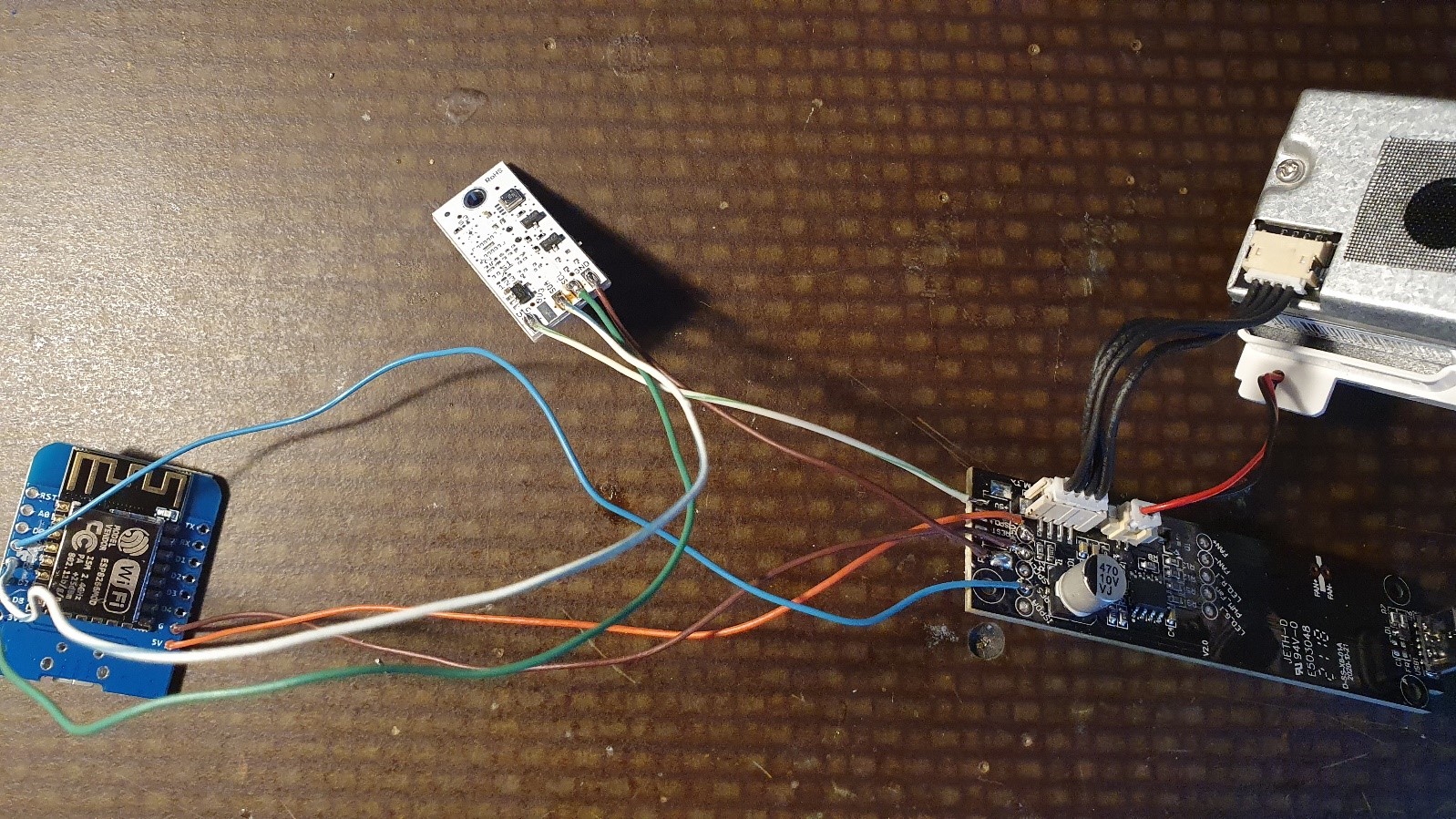
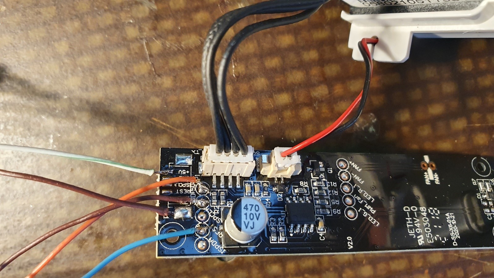
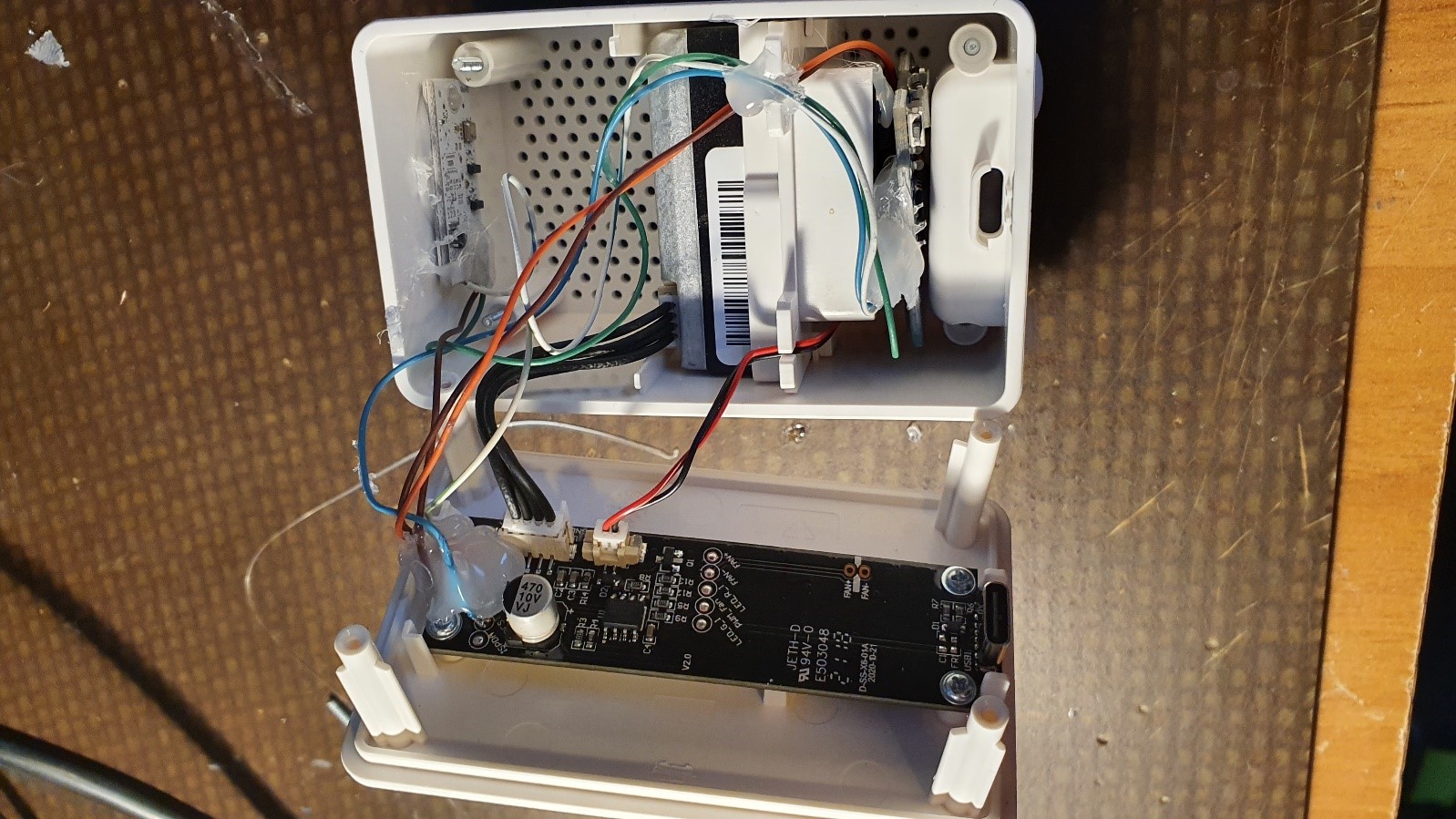
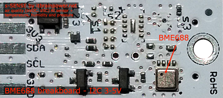
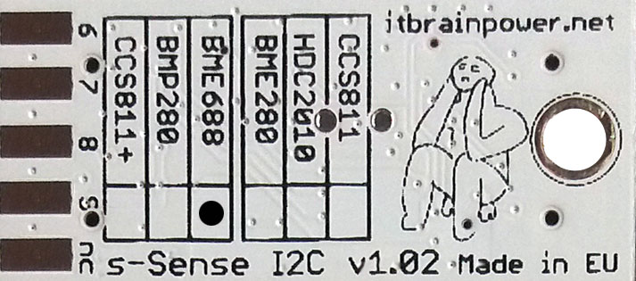
PN: SS-BME688#I2C SKU: ITBP-6007 BME688 I2C sensor breakout more info, order
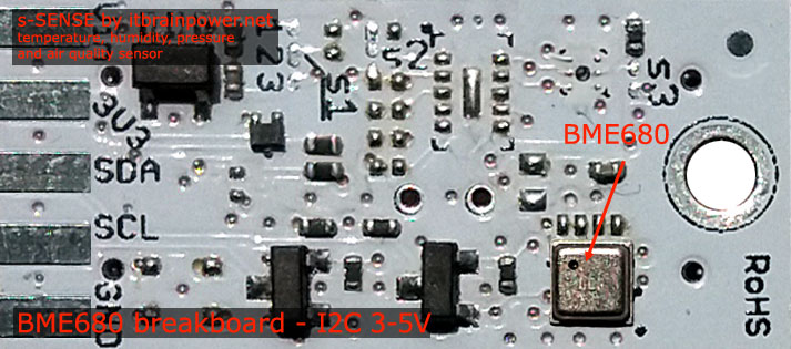
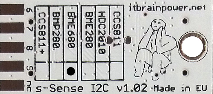
PN: SS-BME680#I2C SKU: ITBP-6003 BME680 I2C sensor breakout more info, order
TUTORIAL PROVIDED WITHOUT ANY WARRANTY!!! USE IT AT YOUR OWN RISK!!!!