i-hatGSM3G Raspberry PI adapter common opperation
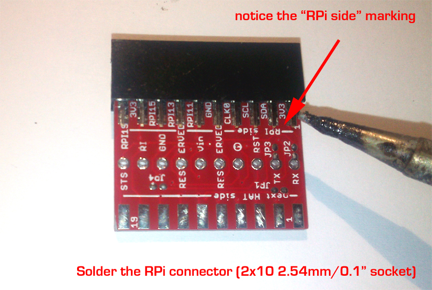
Solder the Raspberry PI side connector

Notice the PCB side and connector position in picture up-here. Use it as reference
a. Select the 2x10 2.54mm (0.1") pin-header socket received the i-hatGSM3G in bundle. Try to decrease a little bit the distance between the two row pins/terminals (press the connector gentily on flat surface, one terminal row in direction of the other row) - this will help you at soldering stage.
b. Place the socket header on the edge (RPI side)of the i-hat3GGSM PCB (insert the PCB between the 2 pin/terminal rows). HINT: you may secure the connector position for soldering using one clip.
c. Solder the socket terminals on one side, turn the PCB and solder the terminals on the other PCB side.
d. Check for short-circuites.
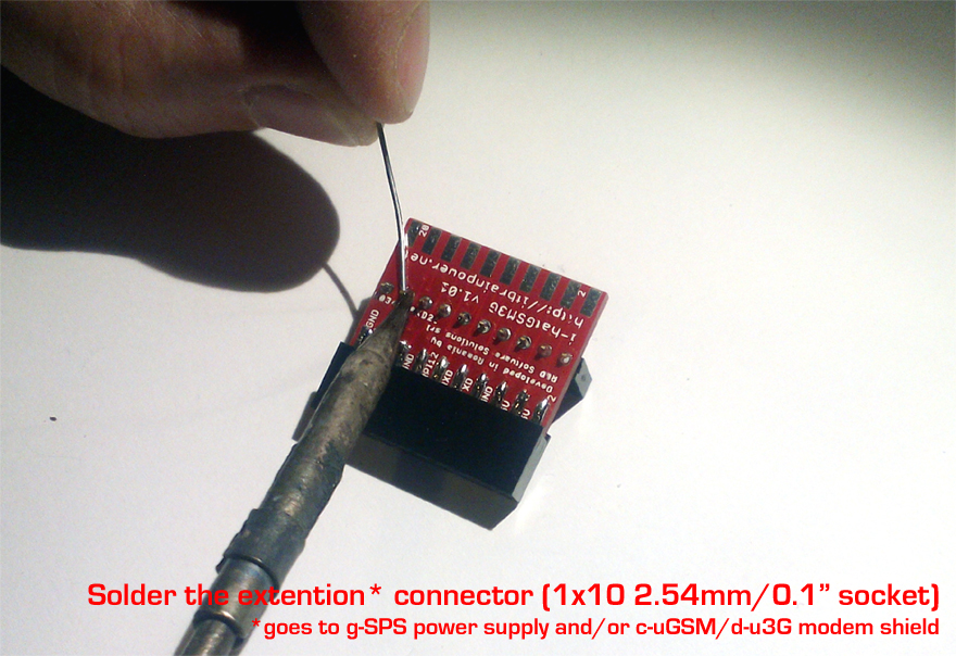
Solder the extension connector (to the 3G / GSM shield)

Notice the PCB side and connector position in picture up-here. Use it as reference
a. Select the 1x10 2.54mm (0.1") pin-header socket received the i-hatGSM3G in bundle.
b. Insert it into the extention of i-hat3GGSM PCB. Notice the side.
c. Solder the socket terminals.
d. Check for short-circuites.
g-SPS switching power supplies preparation (optional - dependes on configuration chosen)
Solder the g-SPS 5V [LiPOL] connectors
![g-SPS 5V [LiPOL] with connectors soldered- click to enlarge g-SPS 5V [LiPOL] with connectors soldered](../images/g-SPS-LiPOL-with-connectors_880px.jpg)
Solder the 10 x 2.54mm(0.1") pinheader and 10 x 2.54mm(0.1") pinheader-socket as in previous picture.
HINT: You can use 2.1mm/2.5mm barel jack connector or 2x2.54mm(0.1")pinheader for power input interface connector, at your convenience. See g-SPS references.
Check for short-circuites after soldering.
Solder the g-SPS 4V [DDRV] connectors
![g-SPS 4V [DDRV] with connectors soldered- click to enlarge g-SPS 4V [DDRV] with connectors soldered](../images/g-SPS-DDRV-with-connectors_880px.jpg)
Solder the 10 x 2.54mm(0.1") pinheader and 10 x 2.54mm(0.1") pinheader-socket as in previous picture.
HINT: You can use 2.1mm/2.5mm barel jack connector or 2x2.54mm(0.1")pinheader for power input interface connector, at your convenience. See g-SPS references.
Check for short-circuites after soldering.
Depending on desired configuration, you chose one / none from the g-SPS variants.
Next, goes see some available configurations. On each variant, I will show to you how i-HAT3GGSM solder-jumpers must set.