Hardware connections
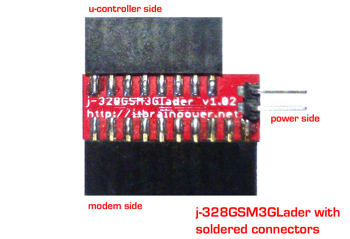
Solder the extension connectors into the modem side and into the u-controller side
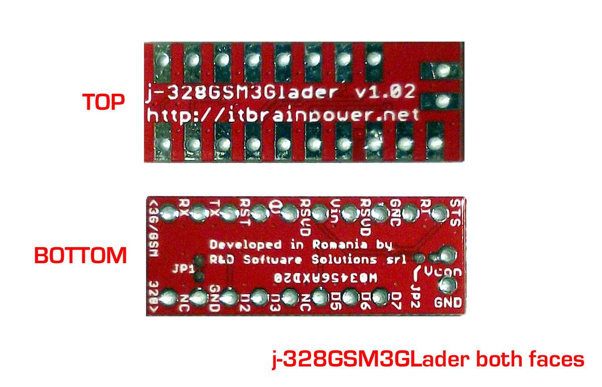
Notice the PCB sides in picture up-here.
HINT: The boards design gives you the posibility for various 3D connetivity options. Bellow we present bellow the "single plane (2D) variant".
a. Select the 1x10 2.54mm (0.1") pin-header socket received the j-328GSM3GLader bundle.
b. Solder it into the modem side of the j-328GSM3GLader PCB. Solder on the BIG PADS (TOP face) recomended.
c. Select the 1x8 2.54mm (0.1") pin-header socket received the j-328GSM3GLader bundle.
d. Solder it into the u-controller side (marked as "328" on the PCB) of the j-328GSM3GLader PCB.
e. Solder one 1x2 2.54mm (0.1") pin-header into the power side (optional) of the j-328GSM3GLader PCB.
f. Check for short-circuites.
We are almost there...
Hardware configuration
Check the hardware reference for your board an identify the pinout as following:
GND, D2, D3, D4, D5, D6 and D7 (D4 not used). If GND is missing [some example boards: a-star mini, Metro Mini 328, Pro Trinket...]>> check bellow for "NO GND workaround"). Else LEAVE JP1 as is (DEFAULT circuit closed - connected).
Solder some 2.54mm (0.1") pin headers into the Ardruino Pro Mini PINS identified before. For this ("single plane / 2D") variant, use 90degrees pin headers.
Having up-here picture as reference:
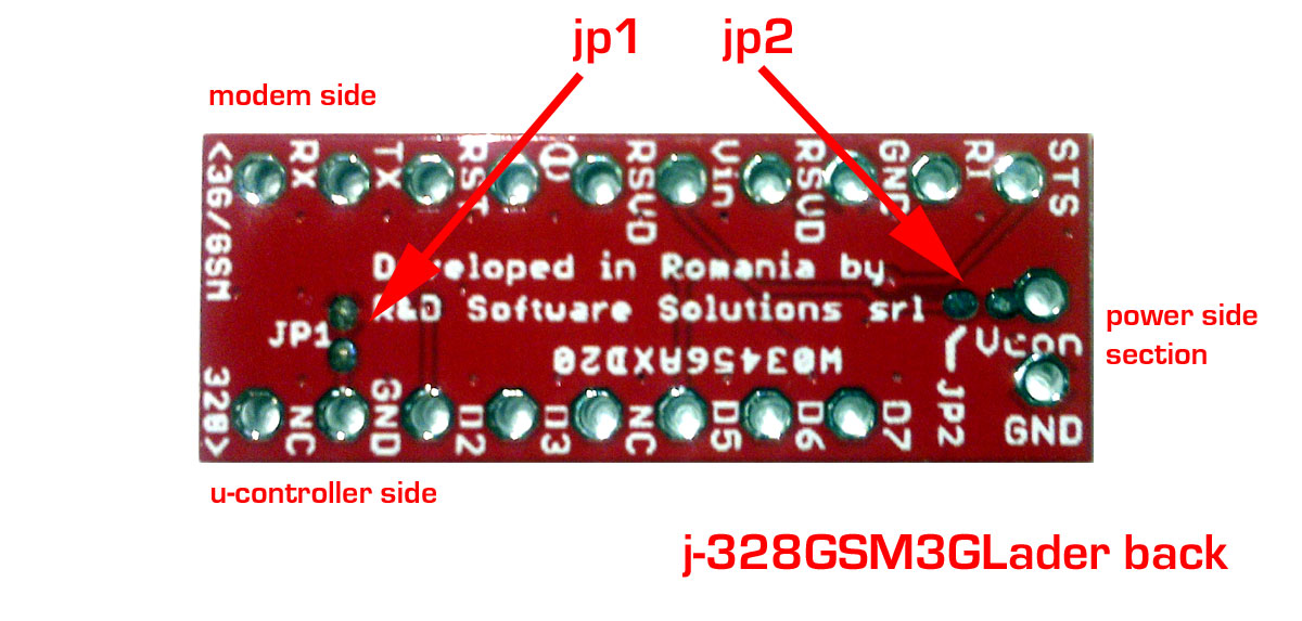
Power config a. Modem no powered from outside (runs on LiPOL battery, only) >> leave JP1 as is (DEFAULT circuit open - not connected). Connect the Lithium Polimer batterry to the modem. This one will be powerer only from the Lithium Polimer batterry. In this way, the modem's Lithium Polymer charger it is not powered and not used!
Power config b. Power the modem via "Power side section" connector >> make short on the solder jumper JP1. On Vcon you may supply +5V. Modems will be used with Lithium Polimer batterry connected. In this way, the modem's Lithium Polymer charger it is powered and used!
Power config c. Power the modem via "modem's USB" connector >> make solder short between LEFT RSVD (placed between I/O and Vin pads) pad and Vin pad; make short on the solder jumper JP1 ONLY if you want to export Vusb via Vcon pad ("Power side section") . On Vcon you may supply +5V. Modems will be used with Lithium Polimer batterry connected. In this way, the modem's Lithium Polymer charger it is powered and used!
HACKS
The power and configuration options are not limited -see some HACKS bellow:
WARNING: Same, the posibilities to destroy your hardware are not limited! BE SURE YOU KNOW WHAT YOU ARE DOING!
NO GND workaround - using a cutter, carefully cut/interrupt the GND between the two pads of the solder-jumper JP1.
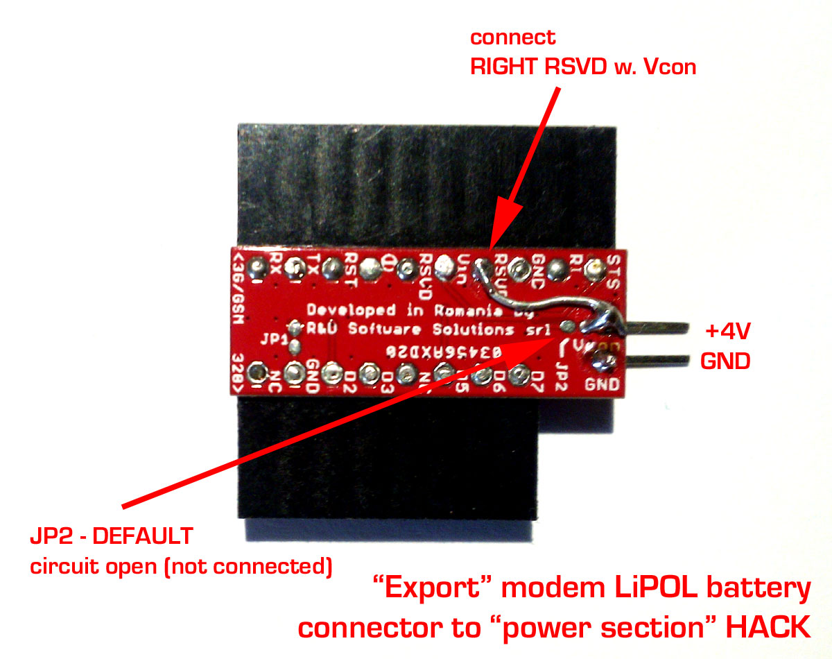
Route the modem's +4V in/out (Lithium Polymer battery) trough the "Power side section" HACK.
Leave JP2 unsoldered (as circuit open). Solder one small wire between the right pad of the JP2 (or Vcon pad) and the RIGHT RSVD pad (bellow picture).
Connecting the boards. Some hardware configurations examples
Before examples, IMPORTANT! Keep in mind, when you connect the boards:
a. j-Lader to Arduino Pro Mini align boards having as D7 as reference pin
b. modem to j-Lader align boards starting with the RX pin
Hardware examples, bellow:
a. Straight connection between Arduino Pro Mini and 3G or GSM modular modem
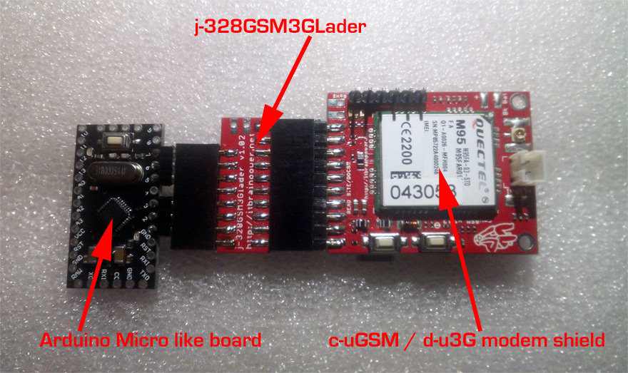
This configuration it is valid for h-nanoGSM shield, too. For modem powering, see up-there in this page.
b. Connection between Arduino Pro Mini, 3G or GSM modular modem and g-SPS switching power supply
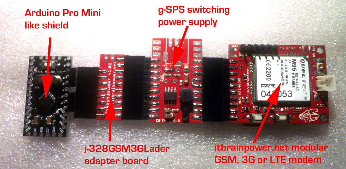
Same configuration as above, but g-SPS power supply was inserted between the GSM/3G modem and Arduino Pro Mini board.
Select g-SPS 4V version [DDRV], if you would like to use your modem without Lithium Polymer battery, or
g-SPS 5V version [LiPOL], if you would like to use your modem with Lithium Polymer battery.
This configuration it is valid for h-nanoGSM shield, too.
Power the Arduino Pro Mini from the same power source
The idea is to use an external 5V power supply to power the modem (ex: use g-SPS 5V source + Lithium Polymer battery or direct 5V power as .Power config b. or .Power config c. described earlier).
If your Arduino Pro Mini (like) board is rated for 5V, the only thing to do is to solder one wire from the j-328GSM3GLader +5V PAD (marked as Vin) to the Arduino Pro Mini +5V IN (usually marked as Vcc . check your board documentation!).
The second case is the same as above, but your Arduino Pro Mini is instead rated at 3.3V. The solution would be the same as above, but connect to the Arduino Pro Mini.s RAW pad! An alternative is to connect using one 1N4148 diode, in direct polarization, to the MODEM VCC +4V pad [or corresponding j-328GSM3GLader PAD] to the Arduino Pro Mini +3V3 IN (usually marked as Vcc . check your board and other electronics inter-connected documentation!).Warning: the voltage that powers the Arduino Pro Mini will provide around 3.2-3.4V, but may very widely!
The same approach can be used as in second case and applied for the .Power config a. and using Arduino Pro Mini 5V version. Instead of an 1N4148 diode, use one plain wire (we.ve tested several Mega328p/16V down to 3.2V and even lower @ room temperature).
As conclusion, always read first and solder later, and double check what you are doing! The j-328GSM3GLader and itbrainpower.net modular modems offer support for multiple powering schemes and (almost) endless hacking.
Connecting sensors and actuators
On the Arduino Pro Mini board there are additional IO available for connecting sensors and actuators. D4, D8->D13 digital pins and A0->A3 analog pins are unused and free to use however you want. Just adapt your project / code in order to use those interfaces for sensors and actuators to complete your specific project.
Software configuration
All ARDUINO software support examples, available in DOWNLOAD section, published starting with 2016, August supports natively the j-328GSM3GLader Arduino Pro Mini adapter board.
All you need to do is to remove comment for "#define usejLader" compiling directive (or to add this one) in the software example.
For older software version, for your original code, or in Python examples, you may define the connectivity as following (regardless you use c-uGSM, d-u3G or h-nanoGSM modular shiels):
RX => D3
TX => D2
POWERON => D7
RESET => D6
STATUS => D5
ENJOY!
TUTORIAL & SOFTWARE ARE PROVIDED WITHOUT ANY WARRANTY!!! USE IT AT YOUR OWN RISK!!!!
