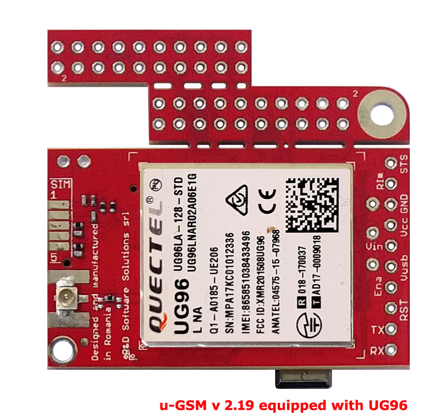
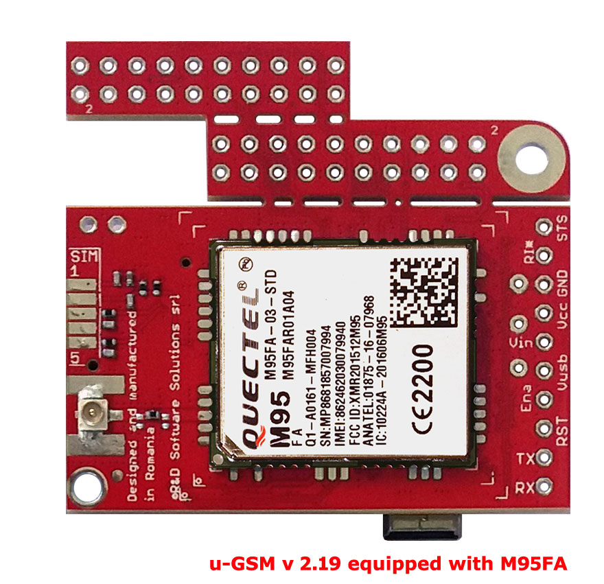
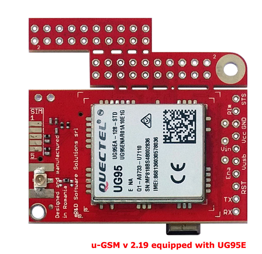
itbrainpower.net u-GSM shield it is the worldwide first (and the only one) modular modem that supports ALL deployed GSM standards [LTE NB IoT / LTE CATM1 / LTE CAT4 / LTE CAT1 / UMTS-3G / GSM-2G] in one unified design!

Popular SBCs [Raspberry PI (all B type GPPIO interface versions - RPI B+/II/Zero/3) and Beagle Bone Black] are supported directly trough integrated interfaces. The embedded LiPo battery / LiIon battery / super-capacitor charger enables u-GSM to be powered directly from RPI / BBB 5V PINs!!!.
About this tutorial
This tutorial addresses the hardware integration side only, using the u-GSM shield RPI and BBB embedded interfaces. Also, you may like to know how to connect the LiPO battery or the super-capacitor.
For software configuration download and install the support packages from u-GSM shield download section.
Platforms: BEAGLEBONE BLACK, RASPBERRY PI or other SBC having the GPIO header compatible with RPI B+.
Time needed: 5-10 minutes.
Skills required: Soldering.
Additional components required:
- JSP 2pin for LiPo battery + LiPo battery [1 cell having capacity bigger that 150mAh], or
- super-capacitor 0.5-1F / 5V, LOW ESR [<200mOhm] as: SCMT22C505MRBA0 (AVX) and PM-5R0H105-1 (POWERSTOR/EATON).
- for BeagleBone Black >> 2x10 header male ;
- for Raspberry PI >> 2x10 header female;
note@20230327 ==> I stress you again! LiPo/LiION battery OR super-capacitor are REQUIERED for proper u-GSM functionality!!! *
* for low power LTE u-GSM modems used in LTE-CATM or NBIoT mode only [BG95-M2 and BG96/BG95-M3 having 2G mode restricted], the LiPO battery or the super-capacitor can be safely replaced with 1000-1500uF/6.3V LOW ESR capacitor.
References
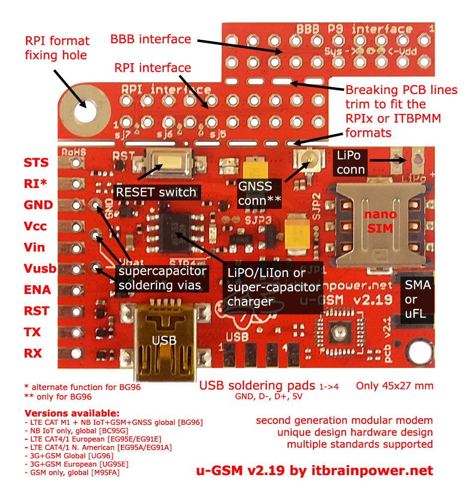
u-GSM shield pinout and jumpers mapping for ITBPMM, RPI and BBB interfaces jpg format
u-GSM shield reference TOP jpg format
u-GSM shield reference BOTTOM jpg format
In images above, notice the Raspberry PI half interface, the BeagleBone Black partial P9 interface and the breaking PCB lines.
u-GSM shield - block schematics rev 1.1 png format
How to trim u-GSM shield PCB in order to fit Raspberry PI case format
This step it is NOT MANDATORY! We suggest you to trim the board ONLY if you want to embbed the Raspberry PI and the u-GSM assembly in a RPI case!
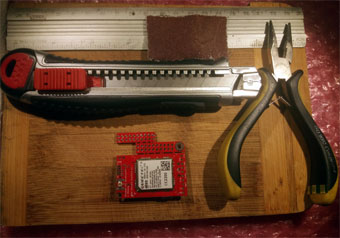
- wooden board
- flat pliers or long nose pliers
- metalic ruler or a piece of PCB
- sand paper
- cutter tool
Cutter tools are very sharp! Take care for your fingers! SAFETY FIRST!!!
Also, you may damage the board...
Ho to do it:
- in long with RPI trimming line cut (at least) twice on each PCB side. No need to apply very much pressure with the cutter blade.
- guide those cuttings using the metalic ruler.
- using your fingers and the pliers just break the PCB.
- smooth edges of the PCB using the sand paper.
- check for non-bonding signals in the line of cut. Magnifying glass will help you to do this.
- use the video bellow as guideline
WARNING: You are the sole responsible of what are you doing! If you are not sure you can do those in safety, you may ask for assistence / help from proffesionals!
u-GSM shield solder the RPI / BBB GPIO connector(s)
Raspberry PI

In the image up-here, notice:
a. The Raspberry PI connector partion is maked [first one, near the RESET connector] on the PCB. In this image, we used a trim PCB [BBB connector partition removed], but same procedure may be applied for full PCB [wo. trimmed BBB partition].
b. The position of the 2x10pin female connector [connector side shall be on the modem side and soldering on the components side].
BeagleBone Black

In the image up-here, notice:
a. The BeagleBone Black connector partion placed on the edge of the PCB [above RPI partition].
b. The position of the 2x10pin male connector [connector side shall be on the modem side and soldering on the components side].
HINT: the u-GSM shield [not trimmed PCB] can be populated simultaneously with both Raspberry PI and BeagleBone GPIO headers! Even in this case, your u-gsm shield will fit perfectly with Raspberry PI or BeagleBone Black.
Solder the LiPO connector on u-GSM shield for Lithium Polymer battery usage [both RPI and BBB]
Skip this, if super-capacitor is used!

Notice:
a. The connector can be place above or underneath PCB. Not all connector types will fit undearneath PCB. Above PCB connector soldering it is recomended!
b. Keep in mind the polarity of the Lithium Polymer /ION battery connector. Place the pair as required.
Double check your solderings for acuracy. Cold solderings may cause issues in modem functionalty.
Raspberry PI
 Align the connectors at first pin for Raspberry PI GPIO connector [right side in previous picture]! .
BeagleBone Black
 Align the connectors at first pin for BBB P9 GPIO connector [left side in previous picture]! .
Align the connectors at first pin for BBB P9 GPIO connector [left side in previous picture]! .
Solder the super-capacitor [both RPI and BBB]
Skip this, if LiPO battery is used!

Notice:
a. The super-capacitor polarity. Polarity of the supercapacitor soldering VIAs and polarity of the LiPO soldering pads.
b. The super-capacitor terminals can be sodered on supercapacitor soldering VIAsor on LiPO soldering pads [RPI only]. Examples bellow on left side - space saver solution and on right side - recommended assembly.
Double check your solderings for acuracy. Cold solderings may cause issues in modem functionalty.


Assemble u-GSM shield with Raspberry PI - video demo
FINAL HINTS:
1. Always double check what you've done, before powering.
TUTORIAL PROVIDED WITHOUT ANY WARRANTY!!! USE IT AT YOUR OWN RISK!!!!
This tutorial is under update! Come back soon, u-GSM to read about USB integration capabilities with Raspberry Pi and BeagleBone Black, alternate powering modes, external SIM support and more!