About this notes
This notes refers to xyz-mIoT shield shortcuts to integration with ESP12F board (how to ad WIFI services to xyz-mIoT shield), no mater what xyz-mIoT PN (with/wo LTE or GSM modem, with/wo sensors) used.
What to prevent: waste your time for searching ESP12F integration docs and for iterative tests... I've spent 3 days on this subject.
Platforms: ARM0 [ATSAMD21G18A] + WIFI[ESP12F - ESP8266MOD by AI-THINKER].
hardware integration (wiring), in a nut shell

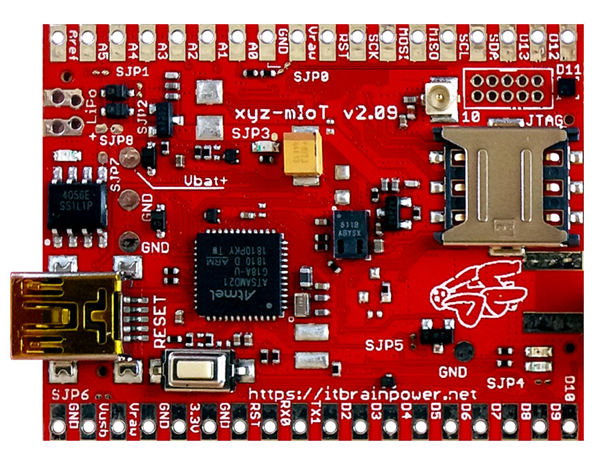
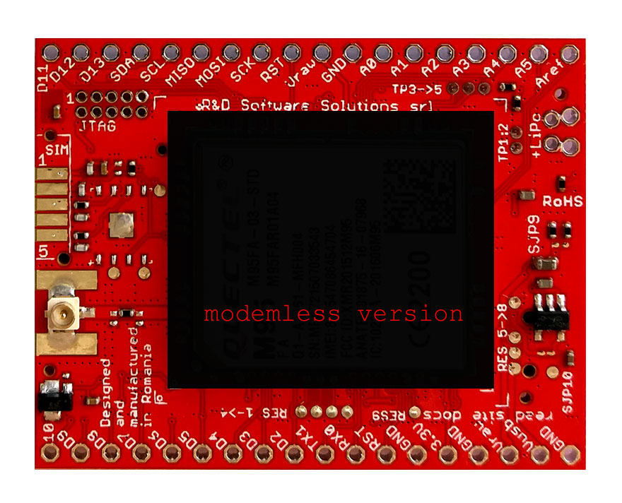
In the image up-here, notice:
a. xyz-mIoT shield powering - please refer to xyz-mIoT documentation.
b. 3.3V power supply for ESP-12F module is provided by xyz-mIoT shield. You may like to add one 0.1uF/1uF ceramic capacitor placed bw 3.3V and GND just near ESP12F 3V3 and GND pads.
c. for production designs, you may like to route ESP12F RST (RESET) to one free digital pin on xyz-mIoT. Default settings as OUTPUT OD (no pull up or pull up). Reset procedure: switch to LOW, wait 250ms, switch back to OD.
d. difference on ESP12F documentation on GPIO00 pullup/pulldown for UART mode / FLASH mode..
Serial comunication hints
- ESP 12F default serial configuration: 115200bps, 8N1.
- each command must be ended by special caracters [CR][LF]
- ALL AT commands must be capitalized.
- xyz-mIoT UART port used: Serial1
AT commands to test ESP12F:
- AT+CWMODE=1
wait 4 OK
- AT+CWJAP="SSID","PASSWORD"
wait 4 WIFI CONNECTED
wait 4 WIFI GOT IP
wait 4 OK
- AT+CIFSR [return IP and MAC]
- AT+CIPSTA? [return IP/GW/MASK]
ESP-12F firmware guidlines
Flashing ESP12F - we've done it using ESP8266_AT_Bin_V1.6.2_0 version, 512+512Kb:
a. download and install "FLASH_DOWNLOAD_TOOLS_v2.3_150916.rar" from here.
b. download and unzip "ESP8266_AT_Bin_V1.6.2_0.zip" firmware from here. Write down the unzip folder path for later use.
c. download "tool_config.txt" from here. Edit downloaded "tool_config.txt" and replace "C:\kits\ESP8266_AT_Bin_V1.6.2" with firmware folder path from previous point. Save edited file.
d. copy edited "tool_config.txt" in firmware folder path.
f. run the flashtool, set you UART PORT and upload the firmware.
Hints:
- ESP-12F GPIO00 resistor must be placed in "FLASH mode".
- one USB-UART(3V3) adapter must be used...and wired to ESP-12F TX and RX.
Additional resources:
- ESP12F datasheet
- ESP8266 AT command examples
- ESP8266 AT commands and AT firmware flashing directives
- xyz-mIoT shield pinout, port map and more pdf format or, in png format
- xyz-mIoT shield - block schematics rev 1.1
TUTORIAL PROVIDED WITHOUT ANY WARRANTY!!! USE IT AT YOUR OWN RISK!!!!