3G / GSM Antenna, LiPO BATTERY [or super-capacitor] INSTALL and typical wiring used in LiPOL battery configuration
d-u3G and c-uGSM shield antenna install
For SMA version of c-uGSM and d-u3G, simply connect the SMA antenna to the SMA edge connector and ignore this step. Following applies to the c-uGSM and g-u3G shields uFL versions.
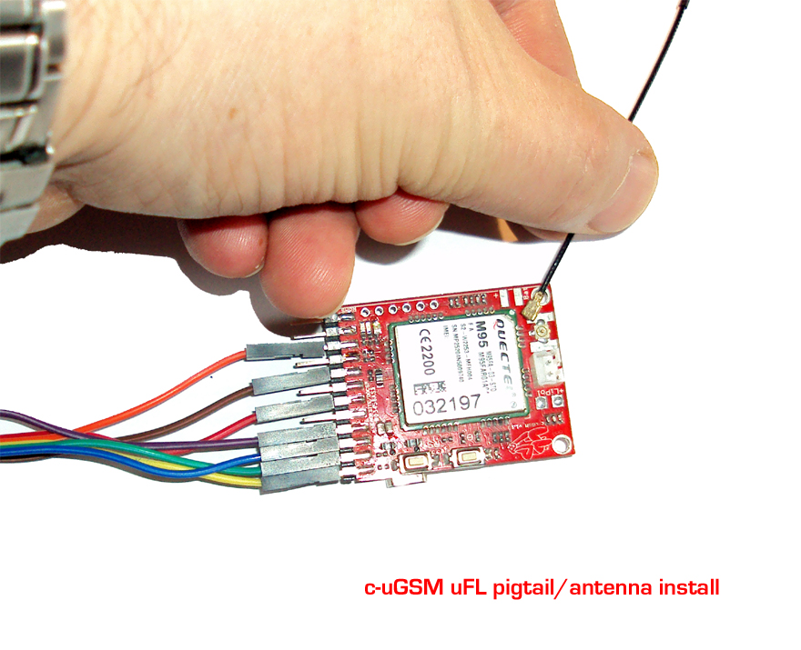
Trying to maintain the alignment coaxiality of the antenna/pigtail cable with the board soldered uFL connector, first approach and then press gently until both connectors fits together.
WARNING: DO NOT APPLY EXCESSIVE FORCE. DO NOT BEND. YOU MAY EASILY DAMAGE YOUR BOARD OR THE CABLE!
In next picture, you can see detail with pigtail uFL connector connected to the board. As next step, you can connect the SMA 3G/GSM antenna to the SMA end of the pigtail.
d-u3G and c-uGSM shield LiPOL battery install

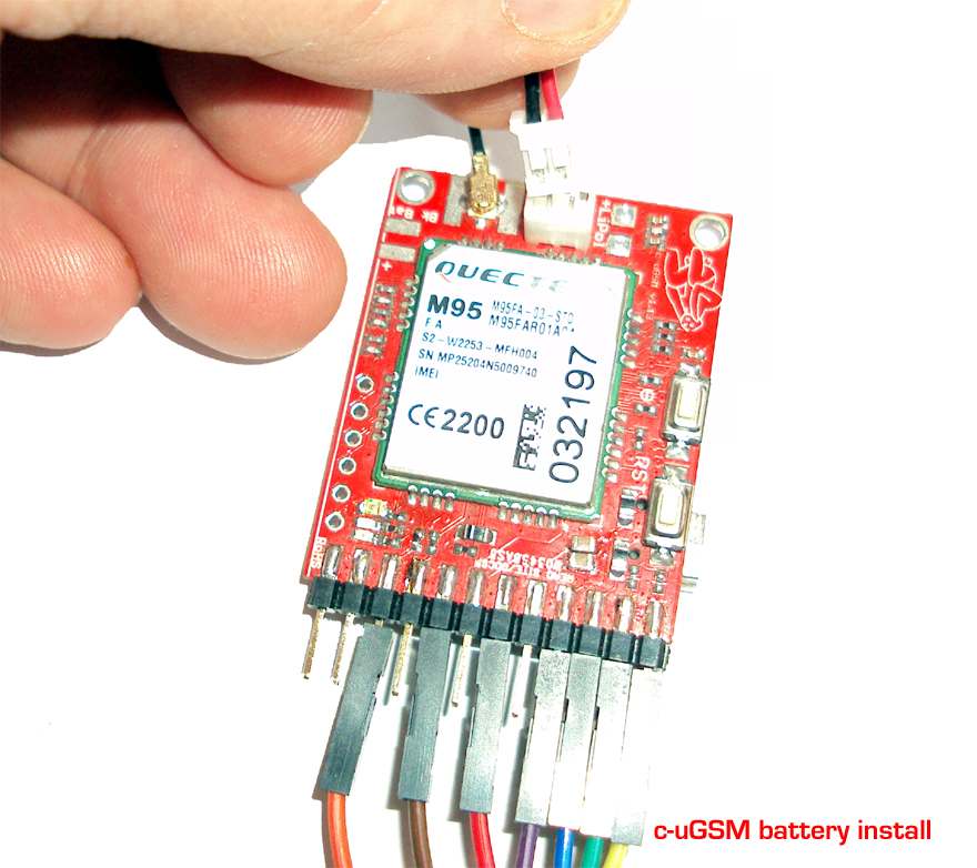
Gentily insert the batterries JST connector to the one soldered to the PCB. As alternative, you can solder directly to the PCB pads the batteries wires.
WARNING: DOUBLE CHECK THE POLARITY. DO NOT SHORT CIRCUIT THE BATTERY!
Hints:
- You can use Lithium Polymer batteries as smallest as 75mAh.
- The Lithium Polymere battery can be replaced with one super-capacitor, bigger than 1F, rated for more than 5V and having ERS lower than 250mOhm. We've made tests using SCMT22C505MRBA0 from AVX and PM-5R0H105-1 from POWERSTOR/EATON.
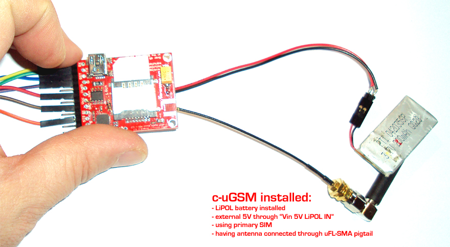
d-u3G & c-uGSM shield - most used LiPOL battery configuration ["WITH Lithium Polymer battery configuration" and VIA Vin (+5V)"]

HINT: Observe here (and in the previous two pictures) the wires connected to the c-uGSM / d-u3G SHIELD "POWERING, SERIAL and CONTROL INTERFACE" and keep it in mind. This configuration is the most used / convenient one for c-uGSM / d-u3G shield with LiPOL battery configuration ["WITH Lithium Polymer battery configuration" and VIA Vin (+5V)"]!
With respect to the conventions presented in the first page, we have:
1. YELLOW wire - RX(TXD)
2. GREEN wire - TX(RXD)
3. BLUE wire - RESET
4. VIOLET wire - POWER ON/OFF (c-uGSM) or POWER ON (d-u3G)
6. RED wire - Vin (5V IN LiPOL IN) - used only in LiPOL configurations powered from external 5V source (as our g-SPS LiPOL).
7. GREY wire - Vcc (4V IN/OUT) - used only in WITOUT LiPOL configurations.
8. BROWN wire - GND(GROUND)
10. ORANGE wire - STS(STATUS)
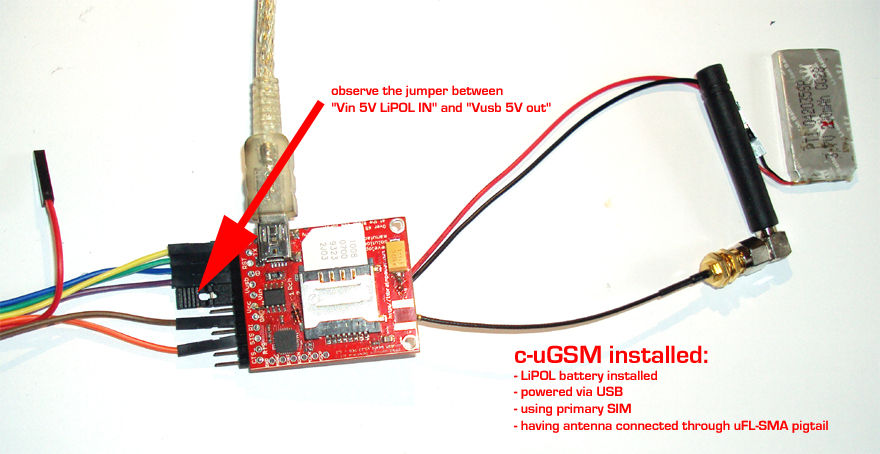
d-u3G & c-uGSM shield - alternative LiPOL battery configuration ["WITH Lithium Polymer battery configuration" and VIA USB (+5V)"]

In this configuration, you can power the d-u3G/c-uGSM shield from USB (your notebook or from the mobile phone wall adapter)
HINT: It is just a variant of previous configuration (just connects the USB +5V to the Vin). Observe the RED wire un-connected and the jumper between PIN 4 (Vusb) and PIN 5(Vin)
Details:
1. YELLOW wire - RX(TXD)
2. GREEN wire - TX(RXD)
3. BLUE wire - RESET
4. VIOLET wire - POWER ON/OFF (c-uGSM) or POWER ON (d-u3G)
7. GREY wire - Vcc (4V IN/OUT) - used only in WITOUT LiPOL configurations.
8. BROWN wire - GND(GROUND)
10. ORANGE wire - STS(STATUS)
JUMPER between "Vusb 5V OUT" and "Vin 5V LiPOL IN"
d-u3G & c-uGSM shield - powering configurations
For "WITHOUT Lithium Polymer battery" powering schema (DDRV), wire as following:1. YELLOW wire - RX(TXD)
2. GREEN wire - TX(RXD)
3. BLUE wire - RESET
4. VIOLET wire - POWER ON/OFF (c-uGSM) or POWER ON (d-u3G)
7. GREY wire - Vcc (4V IN/OUT) - used only in WITOUT LiPOL configurations.
8. BROWN wire - GND(GROUND)
10. ORANGE wire - STS(STATUS)
* The GREY wire (Vcc) must be connected to a power supply (switching power supply recommended) that supplies voltage between 3.6V->4.2V (3.9-4.0V recommended), that drives 0.8A and capable fore more than 1.5A in pulses/spikes. The BROWN wire (GND) must have a branch that connects with the power supply GND.
More information and powering configurations as "Portable stand-alone Lithium Polymer battery", "ONLY Lithium Polymer battery charger" read:
kick-start for c-uGSM 1.13 by itbrainpower.net [ARDUINO GSM shield how to v0.92] (pdf)
or
kick-start for d-u3G 1.13 by itbrainpower.net [ARDUINO 3G shield how to v0.92] (pdf)
Also, you may like to see some GSM/3G shield wiring schema using common Arduino shields and Raspberry PI2/PIB+. Take a look at the next page.