c-uGSM / d-u3G shield wiring schema using common Arduino shields and Raspberry PI2/PIB+
Arduino UN0 connection (wiring) schema with 3G / GSM shield
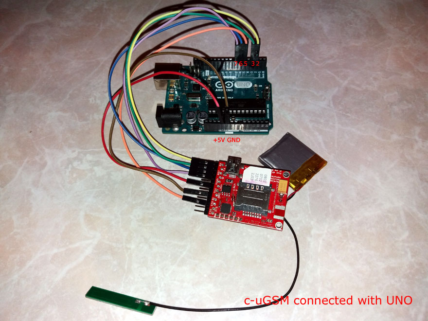
Wiring (color) conventions used as in first page.
The very same wiring applies to the 3G shield d-u3G.
Arduino MEGA2560 connection (wiring) schema with 3G / GSM shield
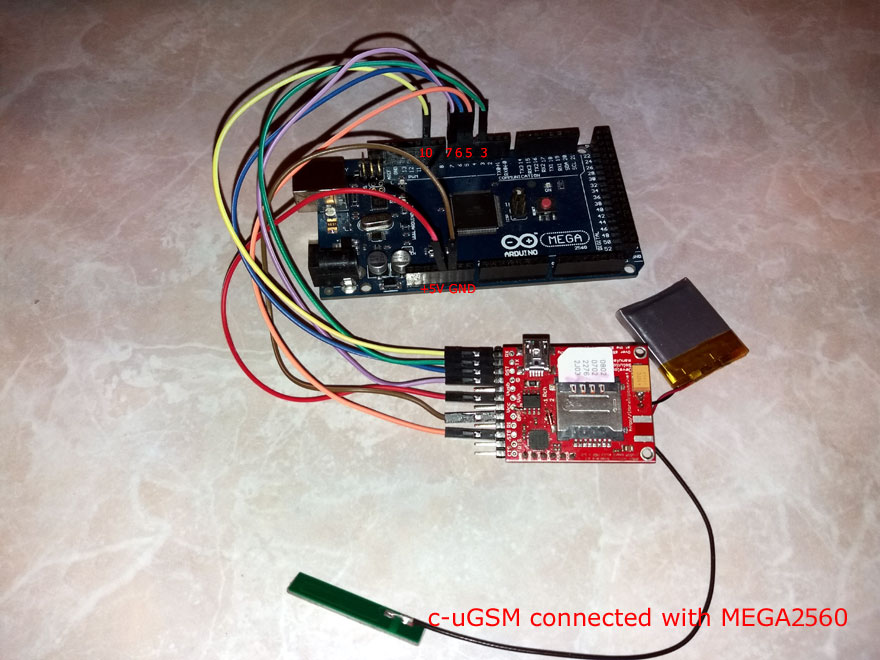
The above picture refers to "SOFTWARE PORT MODE connection" Arduino MEGA2560 , as defined in our Arduino software support files (common used, and default in our files).
Also, the "HARDWARE PORT MODE connection" for Arduino MEGA2560 it is supported (appliable also for Arduino DUE). To do this, follow the wiring as in above picture, but:
* YELLOW - RX(TXD) goes to ARDUINO PIN D18 instead PIN D3
* GREEN - TX(RXD) goes to ARDUINO PIN D19 instead PIN D10
The very same wirings schema applies to the 3G shield d-u3G.
d-u3G & c-uGSM shield - Raspberry PI2 or Raspberry PI B+ SERIAL communication configuration
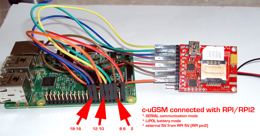
The very same wirings schema applies to the 3G shield d-u3G.
d-u3G & c-uGSM shield - Raspberry PI2 or Raspberry PI B+ USB communication configuration
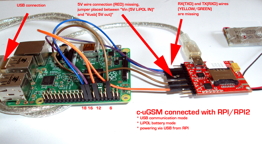
HINTS:
* Observe the USB cable and the YELLOW & GREEN wires are missing. The Raspian OS will recognize the USB serial port as /dev/TTYUSB0 for c-uGSM shield and as /dev/ttyACM0 for d-u3G shield. The data exchange between the RPI and the GSM or 3G shield will be made via USB (you must set "serialCommunicationVia = USBCON" in our Python support files).
* Observe the RED wire un-connected and the jumper between PIN 4 (Vusb) and PIN 5(Vin) - powering it is made via the USB cable.
* Other powering options may be useful (Eg.: powering the RPI and the GSM / 3G shield using separete power --> remove the jumper and connect RED wire to 5 V power supply. Do not forget the GND...)
The very same wirings schema applies to the 3G shield d-u3G.
Information about Raspbian Jessy - c-uGSM and d-u3G support can be found in RASPBERRY PI 3 (and RASPBIAN JESSIE) GSM 3G SERIAL HOW TO.
Check also for c-uGSM and d-u3G shields and Raspberry PI howto using the new i-hatGSM3G RPi hat adapter.
More details on GSM and 3G shields - USB drivers and communication support and Advanced interfacing and wirring info for c-uGSM / d-u3G shield (micro) can be found in first page.
c-uGSM audio howto
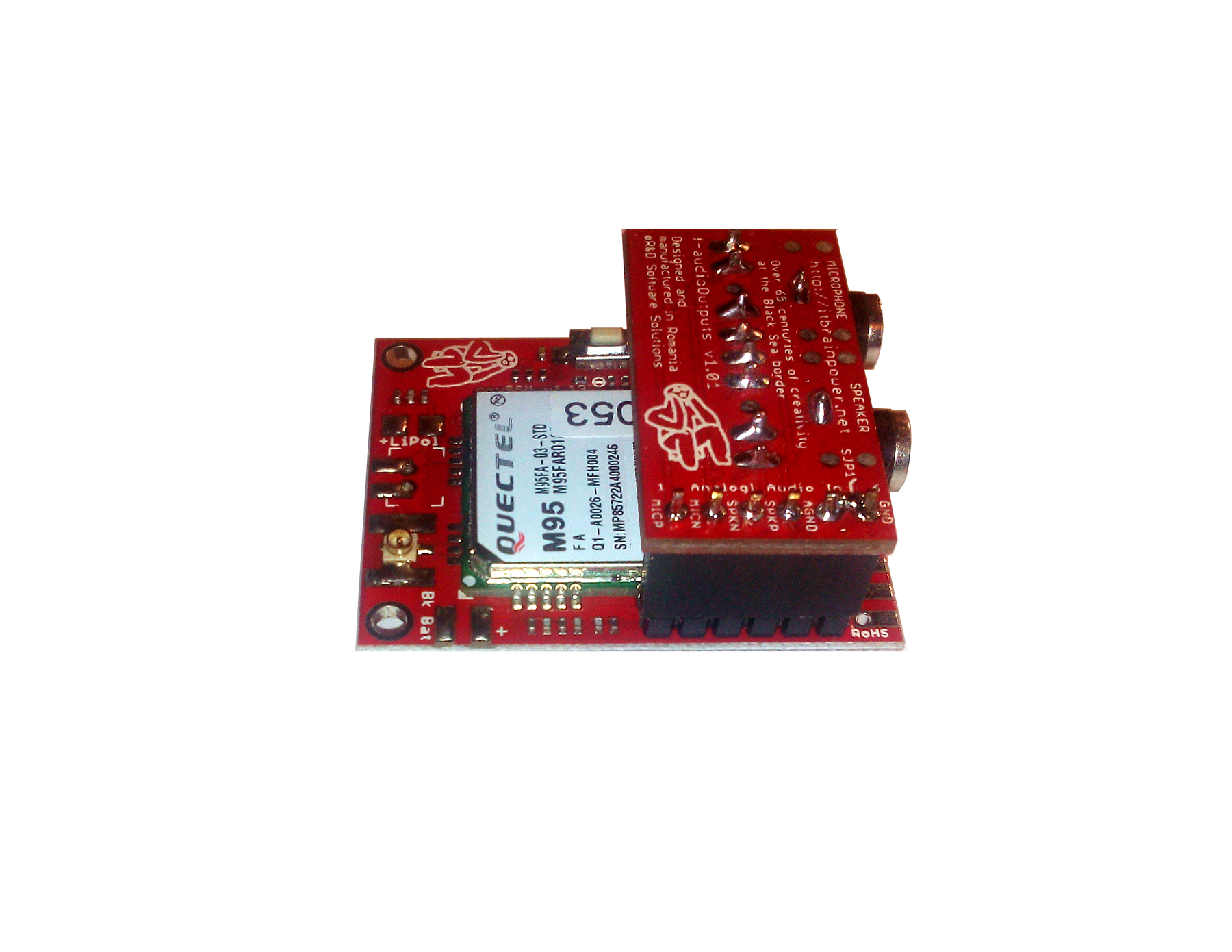
Learn about c-uGSM audio support reading the f-AudioOutputs adapter w. c-uGSM shield howto start tutorial post.
TO BE CONTINUED... Come back soon.