About episode 2 of this project
Next, I will show you how to upload sensor data to cloud using NB IoT UDP and JSON. Our friends from AllThingsTalk (Belgium located CLOUD solution provider) offer free CLOUD based NB IoT services - having very convenient and versatile UDP messaging API (w. JSON, CBOR and ABCL data packing). Really GREAT JOB!
In a nutshell, the xyz-mIoT shield Vbat and Vraw voltages are read and then uploaded to the AllThingsTalk cloud each 120secondes.
u-GSM BC95G shield and Arduino NANO note: If you intend to run this examples using u-GSM BC95G shield, the Vin / Vraw data can be sampled can from Arduino NANO A1 and A2 pins (readVoltages() function in code bellow). To do this, just add #define Vbat A1 and #define Vraw A2 somewhere in the begining of the Arduino code.
Native "NB IOT [UDP mode] itbrainpower.net class" it is used, exactly as in step1. We've choose for UDP data uploading the JSON packing - see in buildJsonPayload() function - adapted for AllThinkTalk UDP data format.
Required time: 10-15 minutes [5-10 minutes if you already performed episode 1 of this demo].
Difficulty: beginner - intermediate.
Bill of materials: the very same as used for episode 1.
Step 1 hardware:
Use the very same hardware as described in NB IoT using BC95G shields epidose1 - steps 1 and 2 If your previously run the NB IoT UDP part 1 test, skip to next step.Step 2 [software download and install. software settings]
Follow the setup steps as described in NB IoT using BC95G shields episode1 - step 3 points a and b. If your previously run the NB IoT UDP part 1 test, skip to next instruction.c. Make a folder named "xyz_mIoT_NBIoT_Class_example_AllThingsTalk".
d. Copy the code bellow, paste it one new file and save the file as "xyz_mIoT_NBIoT_Class_example_AllThingsTalk.ino" in the folder created in previous step.
xyz_mIoT_NBIoT_Class_example_AllThingsTalk.ino
| 1 | /* |
| 2 | xyz_mIoT_NBIoT_Class_example_AllThingsTalk.ino v 0.1/20181016 - upload data [json packed] to AllThingsTalk cloud using UDP service |
| 3 | COPYRIGHT (c) 2015-2018 Dragos Iosub / R&D Software Solutions srl |
| 4 | |
| 5 | You are legaly entitled to use this SOFTWARE ONLY IN CONJUNCTION WITH xyz-mIoT by itbrainpower.net or u-GSM by itbrainpower.net DEVICES USAGE. Modifications, |
| 6 | derivates and redistribution of this software must include unmodified this COPYRIGHT NOTICE. You can redistribute this SOFTWARE and/or modify it under the |
| 7 | terms of this COPYRIGHT NOTICE. Any other usage may be permited only after written notice of Dragos Iosub / R&D Software Solutions srl. |
| 8 | |
| 9 | This SOFTWARE is distributed is provide "AS IS" in the hope that it will be useful, but WITHOUT ANY WARRANTY; without even the implied warranty of |
| 10 | MERCHANTABILITY or FITNESS FOR A PARTICULAR PURPOSE. |
| 11 | |
| 12 | Dragos Iosub, Bucharest 2018. |
| 13 | https://itbrainpower.net |
| 14 | */ |
| 15 | /*IMPORTANT NOTICE 0: |
| 16 | - goto https://maker.allthingstalk.com |
| 17 | - Create one acount, then create one new device [select "your own device"], name it, then add two assets [both sensors, type number] called Vbat and Vin. |
| 18 | - From DEVICES\how_you_named_your_device\SETTINGS\Authentication copy the valus for: "Device ID" and "Device Tokens". |
| 19 | - Use those values in code bellow, to update DEVICE_ID and DEVICE_TOKEN. |
| 20 | |
| 21 | - Use the same hardware setup as described in: https://itbrainpower.net/a-gsm/BC95G-NBIoT-data-transmission-how-to |
| 22 | - if xyz-mIoT shield is used, real voltage sampled data are uploaded to cloud. |
| 23 | - if u-GSM shield is used, dummy data will be uploaded to cloud [.. see in code bellow Vbat and Vraw data sampling in readVoltages()] |
| 24 | */ |
| 25 | /*IMPORTANT NOTICE 1: check itbpGSMdefinition.h for line 60&61 and set "__itbpModem__ xyzmIoT" or "__itbpModem__ uGSM"*/ |
| 26 | /*IMPORTANT NOTICE 2: check itbpGSMdefinition.h for line 64&65 and set "__Qmodule__ BC95G" or "__Qmodule__ BG96"*/ |
| 27 | /*IMPORTANT NOTICE 3: in itbpGPRSIPdefinition.h update your NB IoT "APN", "LTE_BAND" [Eg. Vodafone RO use LTE BAND 20] and "numeric network id code" [Eg. Vodafone RO ==> 22601]*/ |
| 28 | /*IMPORTANT NOTICE 4: in itbpGPRSIPdefinition.h set "SERVER_ADDRESS" with value "40.68.172.187" and "SERVER_PORT" with value "8891"- AllThingsTalk UDP server address and port*/ |
| 29 | /*IMPORTANT NOTICE 5: in itbpGSMdefinition.h "MAX_BUFFER_SIZE", "itbpGSMClassDebug" and "atDebug" may help you....*/ |
| 30 | |
| 31 | #include <String.h> |
| 32 | |
| 33 | String message = ""; |
| 34 | #define DEVICE_ID "ltOgAaRCSeGuOfVBxtUwO" //AllThingsTalk Device Id, replace it with your id |
| 35 | #define DEVICE_TOKEN "maker:4NLwOkA7zeQSm0lqFv10pUgDIvDxWmVyzKsPy" //AllThingsTalk Device Token, replace it with your tocken id |
| 36 | |
| 37 | |
| 38 | int samplingPeriod = 120; //interval in seconds between transmissions... keep it > 60 sec [600 second to test some NB IoT signaling] |
| 39 | |
| 40 | float Vbat = 0, Vraw = 0; |
| 41 | |
| 42 | char IMEI [16]; |
| 43 | |
| 44 | #include <itbpNBIoTClass_v0_2.h> |
| 45 | |
| 46 | #define DEBUG(x) {__itbpDebugPort__.print(millis());__itbpDebugPort__.print(" - ");__itbpDebugPort__.println(x);} |
| 47 | #define DEBUGP(x,y) {__itbpDebugPort__.print(millis());__itbpDebugPort__.print(" - ");__itbpDebugPort__.print(x);__itbpDebugPort__.println(y);} |
| 48 | |
| 49 | #if defined (__AVR_ATmega328P__) |
| 50 | int freeRam () { |
| 51 | extern int __heap_start, *__brkval; |
| 52 | int v; |
| 53 | return (int) &v - (__brkval == 0 ? (int) &__heap_start : (int) __brkval); |
| 54 | } |
| 55 | #endif |
| 56 | |
| 57 | // initialize the library instance |
| 58 | aGsmClient client; |
| 59 | |
| 60 | |
| 61 | |
| 62 | unsigned long startTime = 0; |
| 63 | |
| 64 | bool ledState = 0; |
| 65 | |
| 66 | |
| 67 | void setup(){ |
| 68 | #if (__itbpModem__ == xyzmIoT) |
| 69 | delay(10000); |
| 70 | #endif |
| 71 | |
| 72 | __itbpDebugPort__.begin(115200); //start debug port connection |
| 73 | //configure led |
| 74 | pinMode(LED_BUILTIN, OUTPUT); //embedded LED status indicator |
| 75 | digitalWrite(LED_BUILTIN, LOW); |
| 76 | ledState = 0; |
| 77 | |
| 78 | #if defined (__AVR_ATmega328P__) |
| 79 | DEBUGP(F("Free RAM: "), freeRam()); |
| 80 | #endif |
| 81 | |
| 82 | __itbpDebugPort__.println(F("AllThingTalk cloud NBIoT UDP data upload ...let's rock")); |
| 83 | __itbpDebugPort__.flush(); |
| 84 | |
| 85 | client.begin(); |
| 86 | |
| 87 | client.enableClockUpdate(1); //update available at next modem boot |
| 88 | |
| 89 | client.getIMEI(); //IMEI value in client.resp |
| 90 | memset(IMEI,0x00, sizeof(IMEI)); |
| 91 | strcpy(IMEI,client.resp); |
| 92 | DEBUGP(F("IMEI: "), IMEI); |
| 93 | |
| 94 | client.attachGPRS(); |
| 95 | |
| 96 | //let's verify the module date&time function |
| 97 | delay(1000); |
| 98 | client.getRTC(); |
| 99 | DEBUGP(F("time and date: "), client.resp); |
| 100 | |
| 101 | __itbpDebugPort__.println("connecting..."); |
| 102 | |
| 103 | //client.readServerDatagramReply(); |
| 104 | |
| 105 | startTime = millis() + (unsigned long)samplingPeriod*1000;//force send on the spot |
| 106 | } |
| 107 | |
| 108 | void readVoltages(){ |
| 109 | //read voltage |
| 110 | Vbat=analogRead(VbatPin)*0.0065344650650891/*0.0063636363636364*/; //8bit read, value in volts |
| 111 | Vraw=analogRead(VrawPin)*0.0102016129032258; //8bit read, value in volts |
| 112 | __itbpDebugPort__.print(F("Vbat: ")); |
| 113 | __itbpDebugPort__.println(Vbat); |
| 114 | __itbpDebugPort__.print(F("Vraw: ")); |
| 115 | __itbpDebugPort__.println(Vraw); |
| 116 | } |
| 117 | void buildJsonPayload(){ //get sensor data and pack data in JSON |
| 118 | |
| 119 | readVoltages(); |
| 120 | |
| 121 | message=""; |
| 122 | message += String(DEVICE_ID); |
| 123 | message += "\n"; |
| 124 | message += String(DEVICE_TOKEN); |
| 125 | message += "\n{"; |
| 126 | message += "\"Vin\":{\"value\":"+ String(Vraw)+"}"; //first sensor |
| 127 | message += ",";//separator |
| 128 | message += "\"Vbat\":{\"value\":"+ String(Vbat)+"}"; //second sensor |
| 129 | message += "}"; |
| 130 | //__itbpDebugPort__.print(F("datagram formated: ")); |
| 131 | //__itbpDebugPort__.println(message); |
| 132 | } |
| 133 | |
| 134 | |
| 135 | |
| 136 | void loop(){ |
| 137 | int res=0; |
| 138 | if (millis() - startTime < (unsigned long)samplingPeriod*1000){//waiting period |
| 139 | ledState = ! ledState; |
| 140 | if(ledState != 0) |
| 141 | digitalWrite(LED_BUILTIN, HIGH); |
| 142 | else |
| 143 | digitalWrite(LED_BUILTIN, LOW); |
| 144 | delay(500); |
| 145 | |
| 146 | }else{//start transmission |
| 147 | startTime = millis(); |
| 148 | digitalWrite(LED_BUILTIN, HIGH); //show sampling + uploadto cloud |
| 149 | |
| 150 | if (client.connected() || client.connect()){ |
| 151 | __itbpDebugPort__.println(F("send datagram")); |
| 152 | //res = client.sendDatagram(DATAGRAMTOSEND); |
| 153 | buildJsonPayload(); |
| 154 | res = client.sendDatagram(message); |
| 155 | |
| 156 | if(res == 1){ |
| 157 | __itbpDebugPort__.println(F("data was sent")); |
| 158 | |
| 159 | //not really need to wait for server reply. At this time the AllThinksTalk UDP cloud interface does not have datagram reply implemented. |
| 160 | /* |
| 161 | //here waiting for server reply and for network signaling |
| 162 | __itbpDebugPort__.println(F("wait 4 server reply...")); |
| 163 | unsigned long startlisten = millis(); |
| 164 | res = client.listenForNetworkSignaling(samplingPeriod, 1);//wait until receive server reply (samplingPeriod); //wait for server reply; res |
| 165 | if(res>0){ |
| 166 | __itbpDebugPort__.println(""); |
| 167 | __itbpDebugPort__.print(F("reply received>>")); |
| 168 | __itbpDebugPort__.print(client.resp); //server replied data in resp |
| 169 | __itbpDebugPort__.println(F("<<")); |
| 170 | //here wait for network signaling |
| 171 | res = client.listenForNetworkSignaling(samplingPeriod -(int)((millis()-startlisten)/1000), 4);//wait until enter PSM mode |
| 172 | //res = client.listenForNetworkSignaling(samplingPeriod -(int)((millis()-startlisten)/1000), 2);//wait until enter IDLE mode |
| 173 | } |
| 174 | */ |
| 175 | |
| 176 | /* |
| 177 | //other variant to listen for server reply |
| 178 | res = client.listenForDatagramServerReply(samplingPeriod); //wait for server reply; res |
| 179 | if(res>0){ |
| 180 | __itbpDebugPort__.println(""); |
| 181 | __itbpDebugPort__.print(F("reply received>>")); |
| 182 | __itbpDebugPort__.print(client.resp); //server replied data in resp |
| 183 | __itbpDebugPort__.println(F("<<")); |
| 184 | //here wait for network signaling |
| 185 | //res = client.listenForNetworkSignaling(samplingPeriod - res, 4);//wait until ender PSM mode |
| 186 | } |
| 187 | */ |
| 188 | }else{//send datagram command report ERROR |
| 189 | __itbpDebugPort__.println(F("connectivity error...")); |
| 190 | } |
| 191 | }//end connect() |
| 192 | }//end tranmission |
| 193 | |
| 194 | } |
| 195 |
Alternate, you may start the "xyz_mIoT_NBIoT_Class_example_AllThingsTalk" example found in Arduino under "File/Examples/itbpNBIoTClass".
e. Update some settings in h files inside "itbpNBIoTClass":
- in "itbpGPRSIPdefinition.h" update the APN value, using the APN value of your NB IoT provider (In test was: "eggsn-test-3.connex.ro" for Vodafone Romania);
- in "itbpGPRSIPdefinition.h" update the NETWORKID with numeric network id code for your NB IoT provider ("22601" for Vodafone Romania);
- in "itbpGPRSIPdefinition.h" update the LTE_BAND with numeric band code used for NB IoT service (20 - LTE band B20 for Vodafone Romania);
- in "itbpGPRSIPdefinition.h" update the SERVER_ADDRESS and SERVER_PORT with values "40.68.172.187" and "8891" - AllThingsTalk UDP server address and port;
- in "itbpGSMdefinition.h" goto lines 60&61 and choose from declaration __itbpModem__ xyzmIoT or __itbpModem__ uGSM
- in "itbpGSMdefinition.h" goto lines 64&65 and select __Qmodule__ BC95G"
Step3 AllThingsTalk cloud [create new account, new device and associate new sensors]
a. Go to AllThingsTalk cloud and make a new account.b. Select "DEVICES" section, then click on "NEW DEVICE" button.
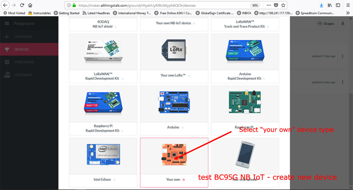
Scroll down the interface and choose "Your own" device. Name the device as: " my amazing xyz-mIoT BC95G NB IoT shield" ;), then click the "CONNECT" button to save the new created cloud device.
c. Create xyz-mIoT shield Vbat and Vin sensors. Click on "CREATE ASSET" and write "Vbat" in "Name" field, then "Choose type" as "number". Confirm new declared sensor (click on "CREATE ASSET").
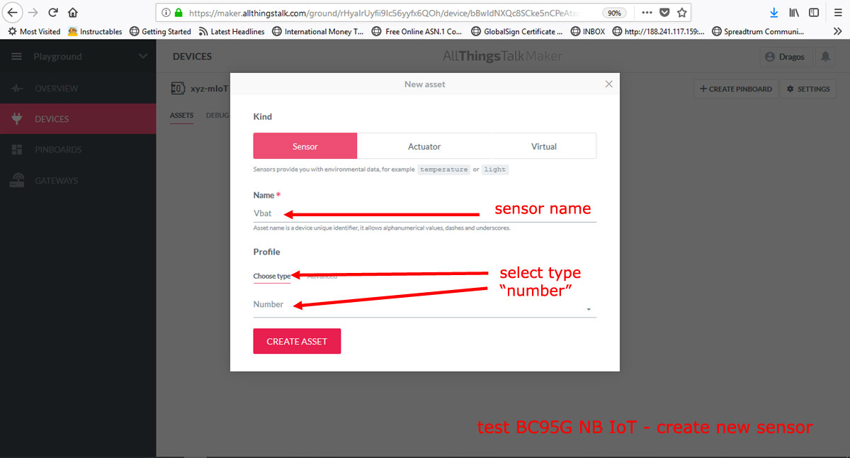
Repeat the same guidelines to declare the "Vraw" as sensor.
d. Copy your new created device token and id. Click on "SETTINGS" button (placed in top-right corner of the screen), click on "Autentication" option.
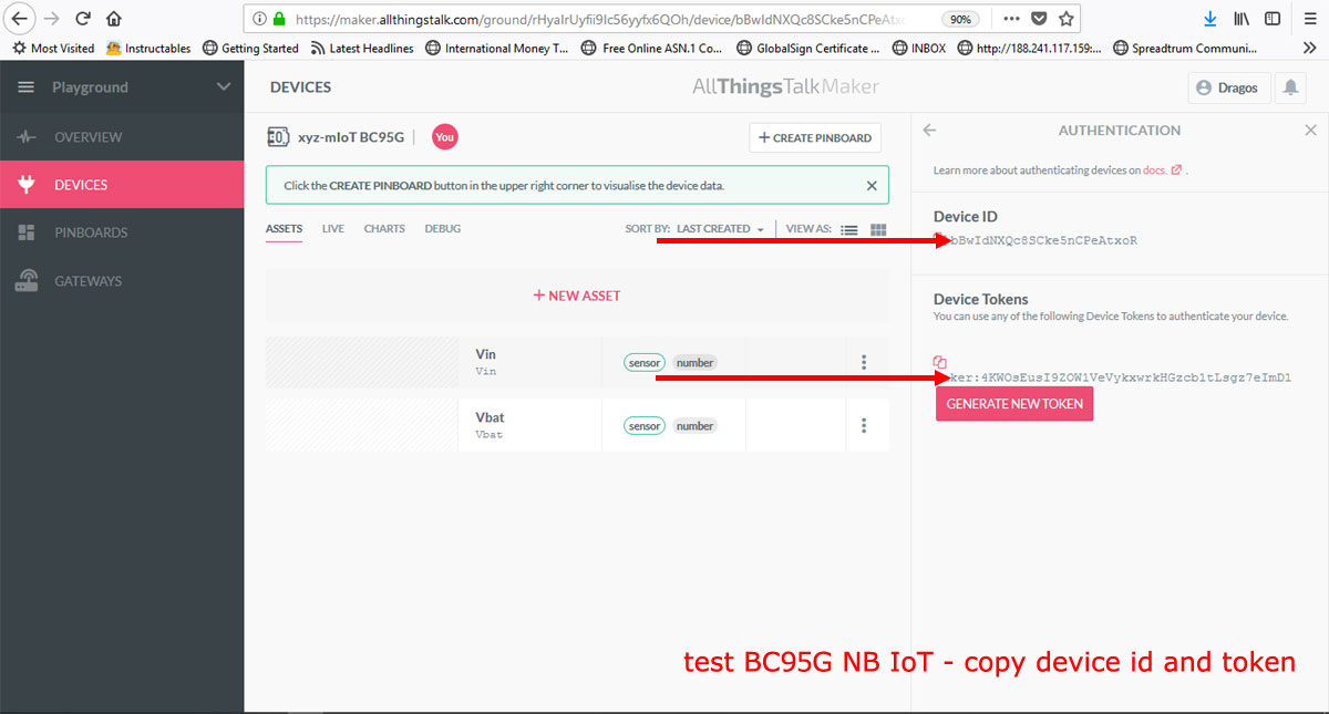
Copy the "Device ID" and "Device Tokens" values and keep them for next step 4 (use those values in the Arduino code as shown below).
Step4 Arduino [compile, upload and run the NB IoT upload sensor data to cloud]
Open in Arduino[(arduino.cc v >= 1.8.5] the xyz_mIoT_NBIoT_Class_example_AllThingsTalk.ino project.
a. Use previously copied "Device ID" and "Device Token" values to setup the "DEVICE_ID" and "DEVICE_TOKEN" parameters in Arduino code.
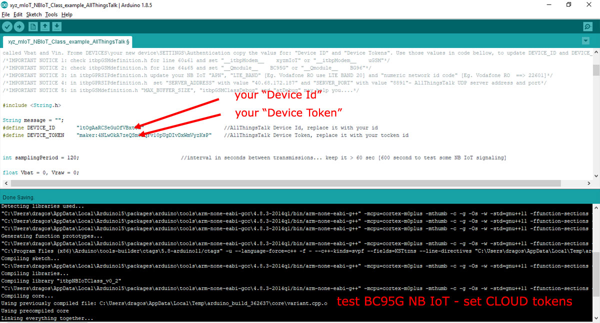
Save the Arduino code. Now all are set for code compiling.
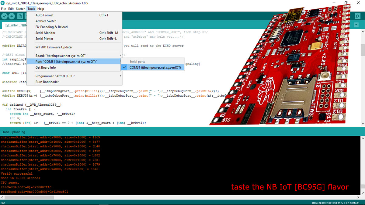
b. Select board [xyz-mIoT shield, or Arduino Nano when run the test with u-GSM shield] and the programming port [bellow, picture example for xyz-mIoT boards].
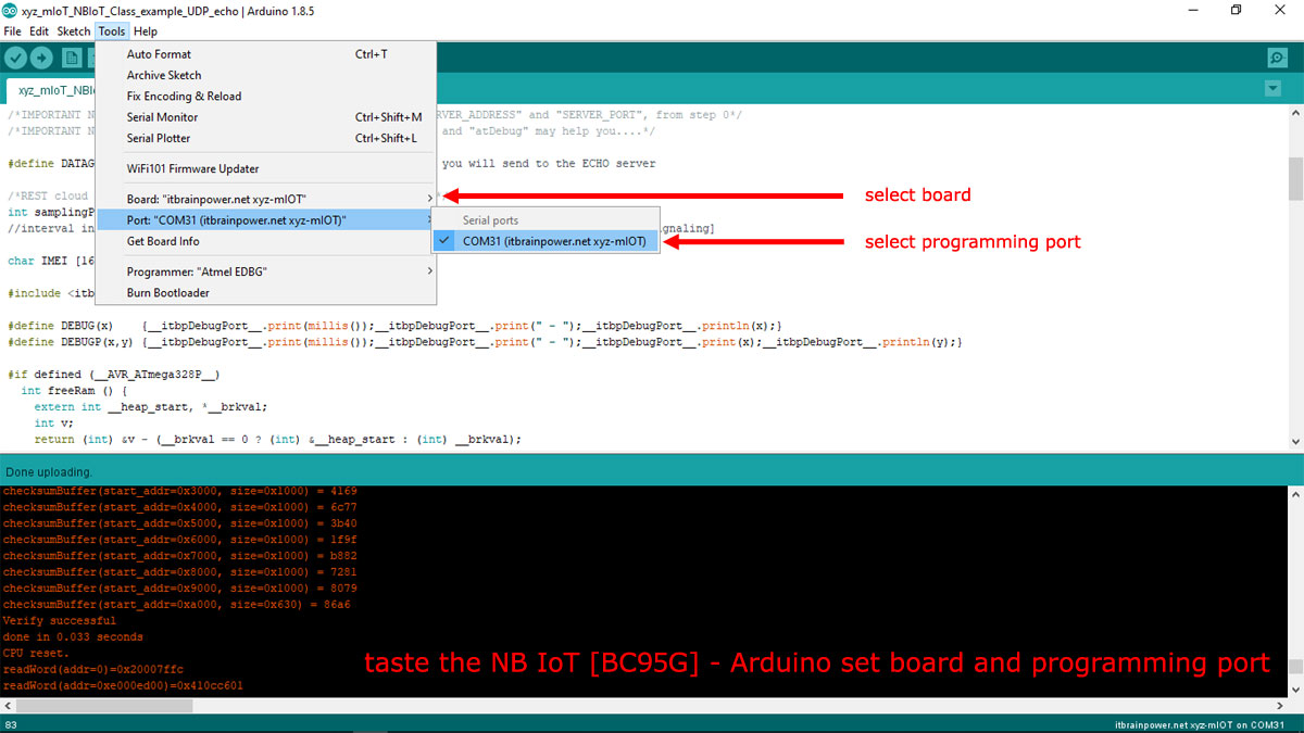
HINT [xyz-mIoT boards only]: In order to upload the code, you must press twice (fast) the xyz-mIoT shield RESET button [the board will switch into programming mode].
c. Compile and upload the code.
In order to visualize the debug output, use the Arduino Serial Monitor or other terminal by selecting the debug port with following settings: 57600bps, 8N, 1.
The xyz-mIoT shield Vbat and Vraw voltages are read and then uploaded to the AllThingsTalk cloud each 120seconds. Uploaded data can be seen in AllThingsCloud interface via "PINBOARD"...btw: create yours.
ENJOY!
TUTORIAL PROVIDED WITHOUT ANY WARRANTY!!! USE IT AT YOUR OWN RISK!!!!
