NB IoT
At September 19'th 2018, Vodafone Romania announced the deployment of their NB IoT network at national level. We welcome the commercial launch of NB IoT technology in Romania and support its use by offering a 35% discount (Romanian customers) on the list price, until 31 December 2018, for our NB IoT products.
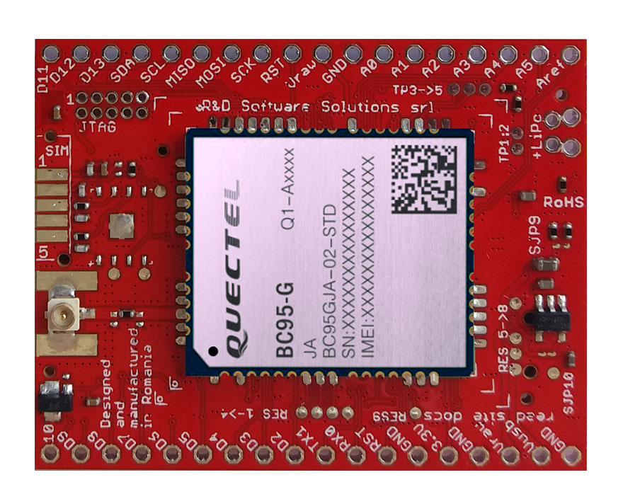
The xyz-mIoT shield may have up to 5 integrated sensors, as: THS (temperature and humidity sensors) - HDC2010, tVOC & eCO2 (air quality sensor - CO2 total volatile organic compounds- CO2 equivalent) - CCS811 , HALL (magnetic sensor) - DRV5032 sau or IR (infrared sensor) KP-2012P3C , secondary IR (infrared sensor) - KP-2012P3C , TILT (movement vibration sensor) or REED (magnetic sensor) - SW200D.
Embedded sensors that populates the xyz-mIoT shield are dependent on PN ordered (check here for available PN).
This NB IoT test will be exemplified with xyz-mIoT shield equipped with Quectel BC95G, PN: XYZMIOT209#BC95-UFL-xxxxxxx.
As alternative, the very same NB IoT tests may be performed using the u-GSM shield equipped with Quectel BC95G, PN: UGSM219-BC95G#UFL.
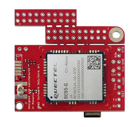
This amazing u-GSM shield may replace all different modem designs by giving to you the same form factor, same interfaces and same integration approach. Just pick the PN that fits your request and that's all.
This second generation modular modem embeds unique and rare features and was brewed thanks to our team design experience, thanks to the vision of Quectel engineers team and to our customers feedback. Some of those amazing features, that makes u-GSM to be the ultimate, the unique and the unbelievable modem, are listed bellow:
- Raspberry PI, Beagle Bone Black and ITBPMM embedded interfaces
- standard, the PCB perfectly fits with Beagle Bone Black but, you can trim the PCB in order to fit the Raspberry PI format, or the ITBPMM format
- the USB port is available via USB soldering PADS and via USB mini B
- external SIM support via sordering PADS
- VIA pads for super-capacitor [or additional capacitor] soldering
- modem power separation [enables modem advanced sleep mode]
- solder jumpers for alternate configuration
About episode 1 of this project
In this post you will find how to use of-the-self xyz-mIOT shield [w. BC95G] or u-GSM shield [w. BC95G] + Arduino mini for data transmision over new NB IoT networks. T minus 15 minutes.Required time: 10-15 minutes. The implementation time may vary depending on previous user experience. Arduino environment installing and manual Arduino class installing are not covered by this how to; try google it. Support libraries and the source code used in this how to are available for download, for registered users, here: xyz-mIoT or u-GSM.
Difficulty: beginner - intermediate.
Bill of materials
-
XYZMIOT209#BC95G-UFL-0000000 [ARM0 + NB IoT modem],
or
UGSM219-BC95G#UFL [NB IoT second generation modular modem] + Arduino Nano shield + some 2.54mm pin-headers and connecting wires. - nano-size [4FF] NB IoT SIM card [we used one SIM from Vodafone Romania]
- 1 x 1000-2200uF /6.3V Low ESR capacitor
- GSM embedded antenna with uFL [check xyz-mIoT / u-GSM accesories] or,
- GSM antenna with SMA plus u.FL to SMA pigtail [check xyz-mIoT / u-GSM accesories]
Step1 [hardware preparation - soldering]:
xyz-mIoT shield [BC95G - NB IoT] - soldering
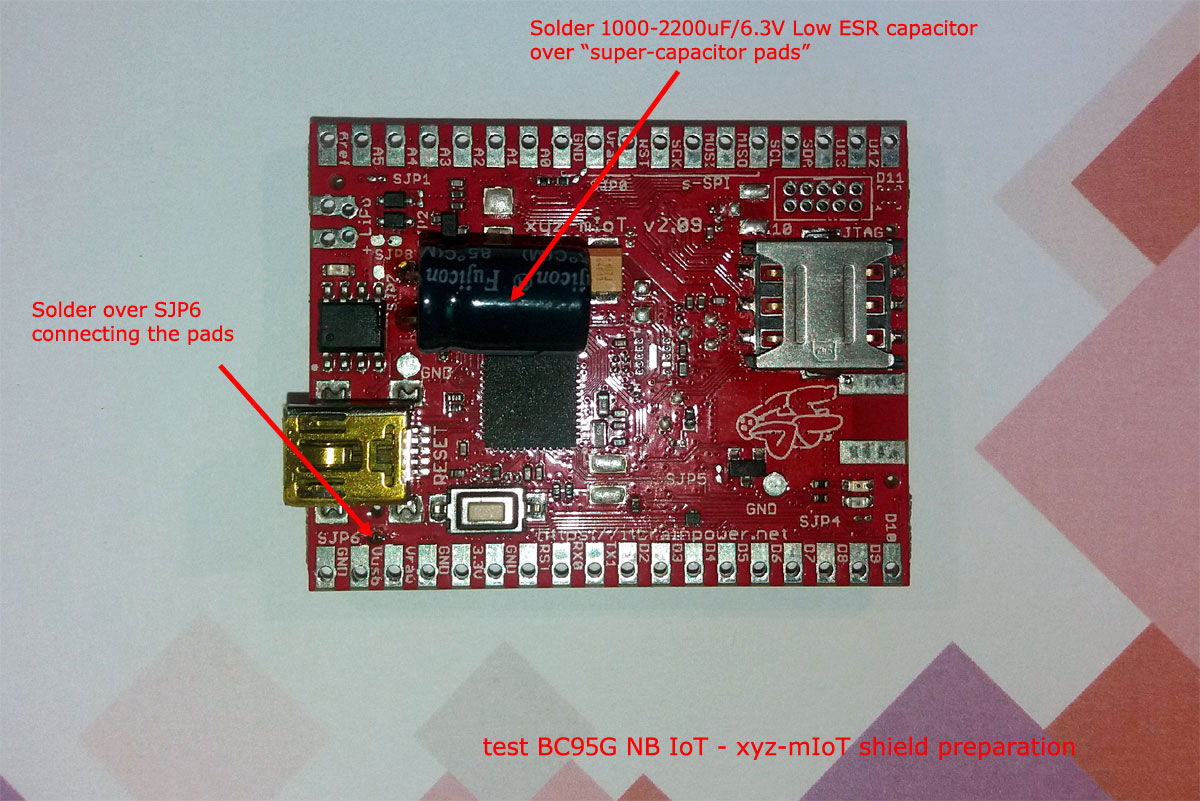
a. Enable 5V from USB to be primary power supply for the xyz-mIoT shield as described up here [solder over SJP6 pads - connect both pads]. Alternative: solder both connectors rows, place the board into one breadboard and connect between Vusb and Vraw using one male-male breadboard wire.b. solder the 1000-2200 uF /6.3V Low ESR capacitor to the "super-capacitor PADS". Keep in mind the capacitor polarity [connect + pole to the Vpad+ pad and - pole to GND pad]!
u-GSM shield [BC95G - NB IoT] - soldering
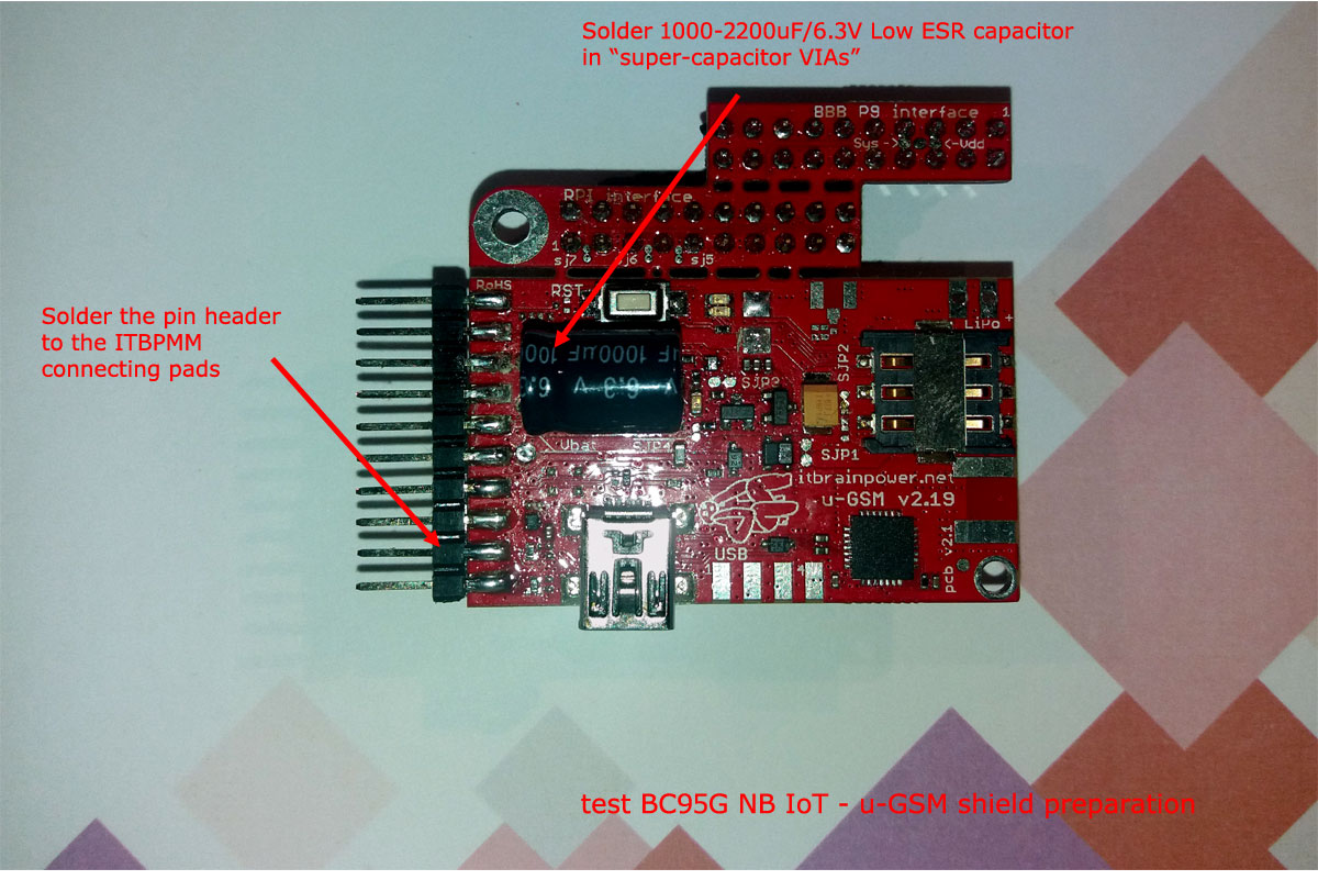
a. solder the pin header [7 x 2.54mm] to ITBPMM interface pads as in picture up-here.b. solder the 1000-2200 uF /6.3V Low ESR capacitor to the "super-capacitor VIAS". Keep in mind the capacitor polarity [connect + pole to the Vpad+ VIA and - pole to GND VIA]!
DOUBLE CHECK YOUR SOLDERINGS!!!.
Step2 [hardware, bring all together]:
xyz-mIoT shield [BC95G - NB IoT] - wiring
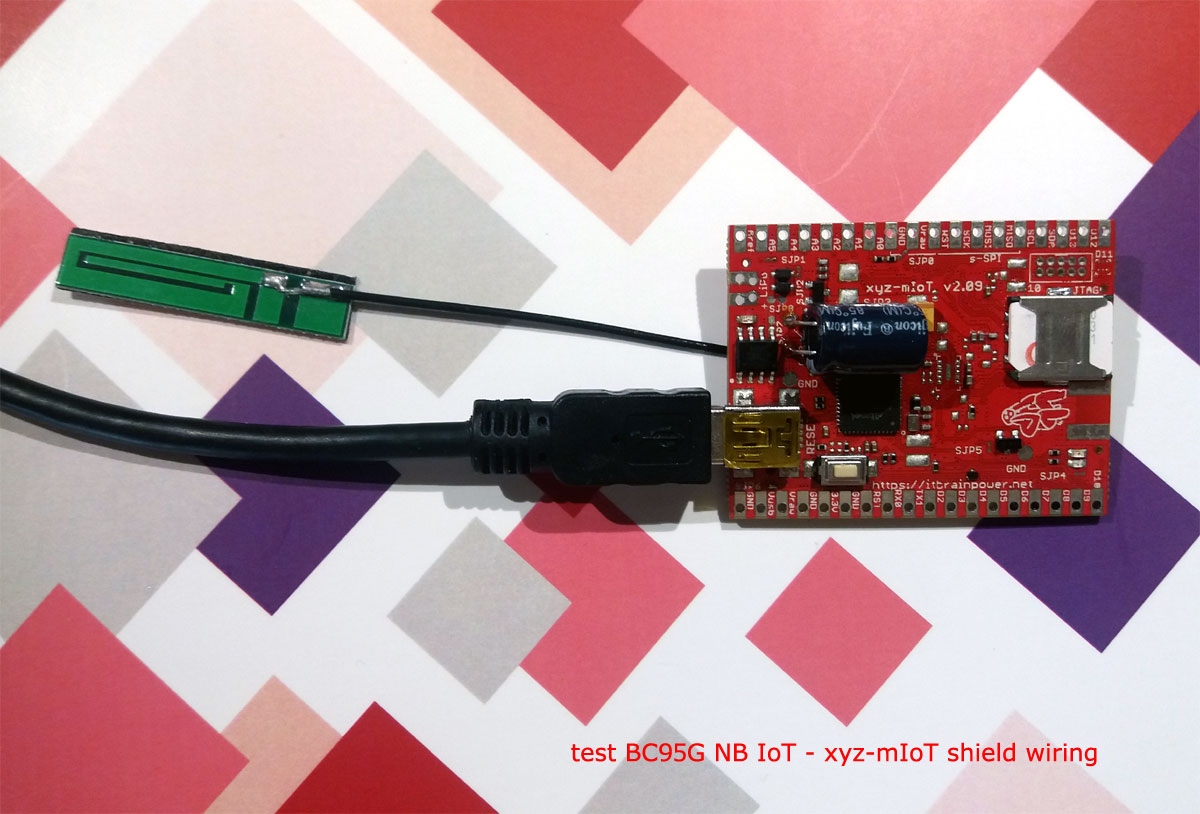
Insert the micro-SIM in his slot [the SIM must have the PIN check procedure removed]. Connect the antenna, then connect the USB cable to xyz-mIoT USB port and to your computer.
The xyz-mIoT shield will be powered from the USB.
u-GSM shield [BC95G - NB IoT] - wiring

Insert the micro-SIM in his slot [the SIM must have the PIN check procedure removed]. Connect the antenna.
Wire u-GSM and Arduino Nano as detailed in picture up-here. Wiring details, bellow:
u-GSM PAD Arduino NANO/UNO
ITBPMM PAD1 - RX(TXD) D2 (Software Serial RX)
ITBPMM PAD2 - TX(RXD) D3 (Software Serial TX)
ITBPMM PAD3 - RST D6
ITBPMM PAD4 - ENA D7
ITBPMM PAD6 - Vin +5V
ITBPMM PAD8 - GND GND
The bundle can be powered [+5V] via Arduino Nano Vcc and GND pins. Anyway, in order to program the Arduino Nano board, this one must be connected to "USB-UART adapter" board. Observe how to connect to CP2102 board adapter, bellow [only Arduino Nano - CP2102 connection are represented]:

This wiring solve Arduino Nano + u-GSM shield powering directly from the USB.

Insert the micro-SIM in his slot [the SIM must have the PIN check procedure removed]. Connect the antenna.
Wire u-GSM and Arduino Nano as detailed in picture up-here. Wiring details, bellow:
u-GSM PAD Arduino NANO/UNO
ITBPMM PAD1 - RX(TXD) D2 (Software Serial RX)
ITBPMM PAD2 - TX(RXD) D3 (Software Serial TX)
ITBPMM PAD3 - RST D6
ITBPMM PAD4 - ENA D7
ITBPMM PAD6 - Vin +5V
ITBPMM PAD8 - GND GND
The bundle can be powered [+5V] via Arduino Nano Vcc and GND pins. Anyway, in order to program the Arduino Nano board, this one must be connected to "USB-UART adapter" board. Observe how to connect to CP2102 board adapter, bellow [only Arduino Nano - CP2102 connection are represented]:

This wiring solve Arduino Nano + u-GSM shield powering directly from the USB.
Step 3 [software download and install. software settings]
If you use u-GSM shield, ignore step a.
a. Download and install "xyz-mIoT shields Arduino class" from xyz-mIoT downlods. Install directives can be found on dowload pages.
b. Download and install "NB IOT [UDP mode] support for xyz-mIoT/u-GSM shields" from xyz-mIoT downloads or u-GSM downloads. Install directives can be found on dowload pages.
c. Make a folder named "xyz_mIoT_NBIoT_Class_example_UDP_echo".
d. Copy the code bellow, paste it one new file and save the file as "xyz_mIoT_NBIoT_Class_example_UDP_echo.ino" in the folder created in previous step.
xyz_mIoT_NBIoT_Class_example_UDP_echo.ino
| 1 | /* |
| 2 | xyz_mIoT_NBIoT_Class_example_UDP_echo.ino v 0.1/20180915 - UDP SEND RECEIVE SOFTWARE EXAMPLE |
| 3 | COPYRIGHT (c) 2015-2018 Dragos Iosub / R&D Software Solutions srl |
| 4 | |
| 5 | You are legaly entitled to use this SOFTWARE ONLY IN CONJUNCTION WITH xyz-mIOT by itbrainpower.net or u-GSM by itbrainpower.net DEVICES USAGE. Modifications, |
| 6 | derivates and redistribution of this software must include unmodified this COPYRIGHT NOTICE. You can redistribute this SOFTWARE and/or modify it under the |
| 7 | terms of this COPYRIGHT NOTICE. Any other usage may be permited only after written notice of Dragos Iosub / R&D Software Solutions srl. |
| 8 | |
| 9 | This SOFTWARE is distributed is provide "AS IS" in the hope that it will be useful, but WITHOUT ANY WARRANTY; without even the implied warranty of |
| 10 | MERCHANTABILITY or FITNESS FOR A PARTICULAR PURPOSE. |
| 11 | |
| 12 | Dragos Iosub, Bucharest 2018. |
| 13 | https://itbrainpower.net |
| 14 | */ |
| 15 | /*IMPORTANT NOTICE 0: install and run "udp_echo.py" listner on your server; write down, for use in step 4, the IP address and UDP listener PORT */ |
| 16 | /*IMPORTANT NOTICE 1: check itbpGSMdefinition.h for line 60&61 and set "__itbpModem__ xyzmIoT" or "__itbpModem__ uGSM"*/ |
| 17 | /*IMPORTANT NOTICE 2: check itbpGSMdefinition.h for line 64&65 and set "__Qmodule__ BC95G" or "__Qmodule__ BG96"*/ |
| 18 | /*IMPORTANT NOTICE 3: in itbpGPRSIPdefinition.h update your NB IoT "APN" and "numeric network id code" [Eg. Vodafone RO ==> 22601]*/ |
| 19 | /*IMPORTANT NOTICE 4: in itbpGPRSIPdefinition.h update your "SERVER_ADDRESS" and "SERVER_PORT", from step 0*/ |
| 20 | /*IMPORTANT NOTICE 5: in itbpGSMdefinition.h "itbpGSMClassDebug" and "atDebug" may help you....*/ |
| 21 | |
| 22 | #define DATAGRAMTOSEND "Mary have a little lamb...." //what you will send to the ECHO server |
| 23 | |
| 24 | /*REST cloud specific, more parameters in itbpGPRSIPdefinition.h*/ |
| 25 | int samplingPeriod = 600; //interval in seconds between transmissions... keep it > 60 sec [600 second to test some NB IoT signaling] |
| 26 | |
| 27 | char IMEI [16]; |
| 28 | |
| 29 | #include <itbpNBIoTClass_v0_1.h> |
| 30 | |
| 31 | #define DEBUG(x) {__itbpDebugPort__.print(millis());__itbpDebugPort__.print(" - ");__itbpDebugPort__.println(x);} |
| 32 | #define DEBUGP(x,y) {__itbpDebugPort__.print(millis());__itbpDebugPort__.print(" - ");__itbpDebugPort__.print(x);__itbpDebugPort__.println(y);} |
| 33 | |
| 34 | #if defined (__AVR_ATmega328P__) |
| 35 | int freeRam () { |
| 36 | extern int __heap_start, *__brkval; |
| 37 | int v; |
| 38 | return (int) &v - (__brkval == 0 ? (int) &__heap_start : (int) __brkval); |
| 39 | } |
| 40 | #endif |
| 41 | |
| 42 | // initialize the library instance |
| 43 | aGsmClient client; |
| 44 | |
| 45 | |
| 46 | |
| 47 | unsigned long startTime = 0; |
| 48 | |
| 49 | bool ledState = 0; |
| 50 | |
| 51 | |
| 52 | void setup(){ |
| 53 | #if (__itbpModem__ == xyzmIoT) |
| 54 | delay(10000); |
| 55 | #endif |
| 56 | |
| 57 | __itbpDebugPort__.begin(115200); //start debug port connection |
| 58 | //configure led |
| 59 | pinMode(LED_BUILTIN, OUTPUT); //embedded LED status indicator |
| 60 | digitalWrite(LED_BUILTIN, LOW); |
| 61 | ledState = 0; |
| 62 | |
| 63 | #if defined (__AVR_ATmega328P__) |
| 64 | DEBUGP(F("Free RAM: "), freeRam()); |
| 65 | #endif |
| 66 | |
| 67 | __itbpDebugPort__.println(F("Simple NBIoT UDP echo example...let's rock")); |
| 68 | __itbpDebugPort__.flush(); |
| 69 | |
| 70 | client.begin(); |
| 71 | |
| 72 | client.enableClockUpdate(1); //update available at next modem boot |
| 73 | |
| 74 | client.getIMEI(); //IMEI value in client.resp |
| 75 | memset(IMEI,0x00, sizeof(IMEI)); |
| 76 | strcpy(IMEI,client.resp); |
| 77 | DEBUGP(F("IMEI: "), IMEI); |
| 78 | |
| 79 | client.attachGPRS(); |
| 80 | |
| 81 | //let's verify the module date&time function |
| 82 | delay(1000); |
| 83 | client.getRTC(); |
| 84 | DEBUGP(F("time and date: "), client.resp); |
| 85 | |
| 86 | __itbpDebugPort__.println("connecting..."); |
| 87 | |
| 88 | //client.readServerDatagramReply(); |
| 89 | |
| 90 | startTime = millis() + (unsigned long)samplingPeriod*1000;//force send on the spot |
| 91 | } |
| 92 | |
| 93 | |
| 94 | |
| 95 | |
| 96 | void loop(){ |
| 97 | int res=0; |
| 98 | if (millis() - startTime < (unsigned long)samplingPeriod*1000){//waiting period |
| 99 | ledState = ! ledState; |
| 100 | if(ledState != 0) |
| 101 | digitalWrite(LED_BUILTIN, HIGH); |
| 102 | else |
| 103 | digitalWrite(LED_BUILTIN, LOW); |
| 104 | delay(500); |
| 105 | |
| 106 | }else{//start transmission |
| 107 | startTime = millis(); |
| 108 | digitalWrite(LED_BUILTIN, HIGH); //show sampling + uploadto cloud |
| 109 | |
| 110 | if (client.connected() || client.connect()){ |
| 111 | __itbpDebugPort__.println(F("send datagram")); |
| 112 | res = client.sendDatagram(DATAGRAMTOSEND); |
| 113 | if(res == 1){ |
| 114 | __itbpDebugPort__.println(F("wait 4 server reply...")); |
| 115 | unsigned long startlisten = millis(); |
| 116 | res = client.listenForNetworkSignaling(samplingPeriod, 1);//wait until receive server reply (samplingPeriod); //wait for server reply; res |
| 117 | if(res>0){ |
| 118 | __itbpDebugPort__.println(""); |
| 119 | __itbpDebugPort__.print(F("reply received>>")); |
| 120 | __itbpDebugPort__.print(client.resp); //server replied data in resp |
| 121 | __itbpDebugPort__.println(F("<<")); |
| 122 | //here wait for network signaling |
| 123 | res = client.listenForNetworkSignaling(samplingPeriod -(int)((millis()-startlisten)/1000), 4);//wait until enter PSM mode |
| 124 | } |
| 125 | /* |
| 126 | //other variant to send |
| 127 | res = client.listenForDatagramServerReply(samplingPeriod); //wait for server reply; res |
| 128 | if(res>0){ |
| 129 | __itbpDebugPort__.println(""); |
| 130 | __itbpDebugPort__.print(F("reply received>>")); |
| 131 | __itbpDebugPort__.print(client.resp); //server replied data in resp |
| 132 | __itbpDebugPort__.println(F("<<")); |
| 133 | //here wait for network signaling |
| 134 | //res = client.listenForNetworkSignaling(samplingPeriod - res, 4);//wait until ender PSM mode |
| 135 | } |
| 136 | */ |
| 137 | }else{//send datagram command report ERROR |
| 138 | __itbpDebugPort__.println(F("connectivity error...")); |
| 139 | } |
| 140 | }//end connect() |
| 141 | }//end tranmission |
| 142 | |
| 143 | } |
| 144 |
Alternate, you may start the "xyz_mIoT_NBIoT_Class_example_UDP_echo" example found in Arduino under "File/Examples/itbpNBIoTClass".
e. Install and run "udp_echo.py" listner on your server; write down, for use in next steps, the IP address and UDP listener PORT.
f. Update some settings in h files inside "itbpNBIoTClass":
- in "itbpGPRSIPdefinition.h" update the APN value, using the APN value of your NB IoT provider (In test was: "eggsn-test-3.connex.ro" for Vodafone Romania)
- in "itbpGPRSIPdefinition.h" update the NETWORKID with numeric network id code for your NB IoT provider ("22601" for Vodafone Romania)
- in "itbpGPRSIPdefinition.h" update the LTE_BAND with numeric band code used for NB IoT service (20 - LTE band B20 for Vodafone Romania)
- in "itbpGPRSIPdefinition.h" update the SERVER_ADDRESS and SERVER_PORT with values UDP echo listener service (from step e.)
- in "itbpGSMdefinition.h" goto lines 60&61 and choose from declaration __itbpModem__ xyzmIoT or __itbpModem__ uGSM
- in "itbpGSMdefinition.h" goto lines 64&65 and select __Qmodule__ BC95G"
Step4 [Arduino compile, upload and run the NB IoT echo test]
Open in Arduino[(arduino.cc v >= 1.8.5] the xyz_mIoT_NBIoT_Class_example_UDP_echo.ino project.
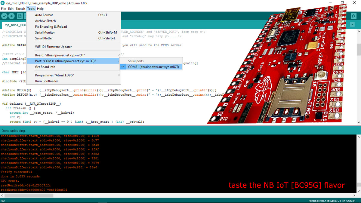
a. In Arduino, select board [xyz-mIoT shield, or Arduino Nano when run the test with u-GSM shield] and the programming port [bellow, picture example for xyz-mIoT boards].
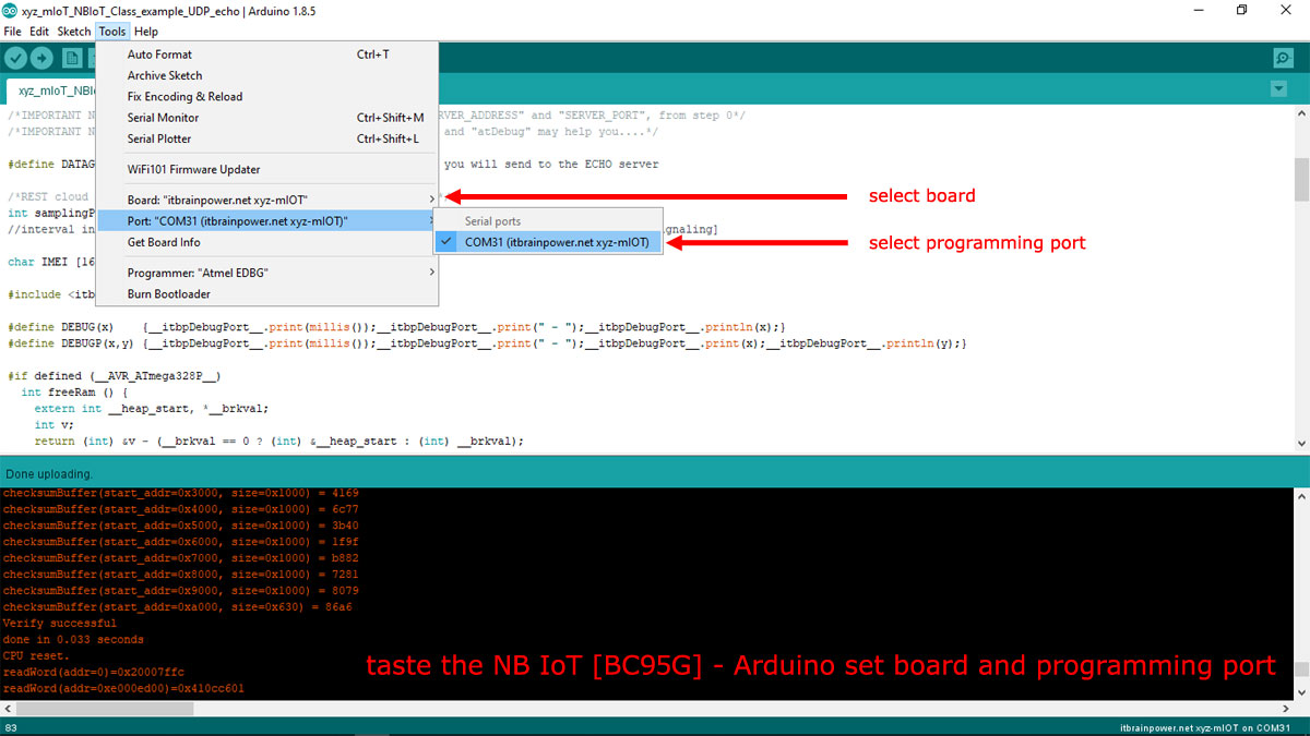
HINT [xyz-mIoT boards only]: In order to upload the code, you must press twice (fast) the xyz-mIoT shield RESET button [the board will switch into programming mode].
b. Compile and upload the code.
In order to visualize the debug output, use the Arduino Serial Monitor or other terminal by selecting the debug port with following settings: 57600bps, 8N, 1.
The xyz-mIoT shield, or Arduino Nano + u-GSM shield bundle, will start to run the code, beeing set at 10minutes NB IoT data exchange rate.
Data data send received and status signaling from the NB IoT network [ENTER/LEAVE ACTIVE, IDLE and PSM modes; also DATAGRAM received] will be visualised in the debuging interface.
ENJOY!
TUTORIAL PROVIDED WITHOUT ANY WARRANTY!!! USE IT AT YOUR OWN RISK!!!!
