About episodes of this project
* Episode 1 - hardware setup required in order to run the software.
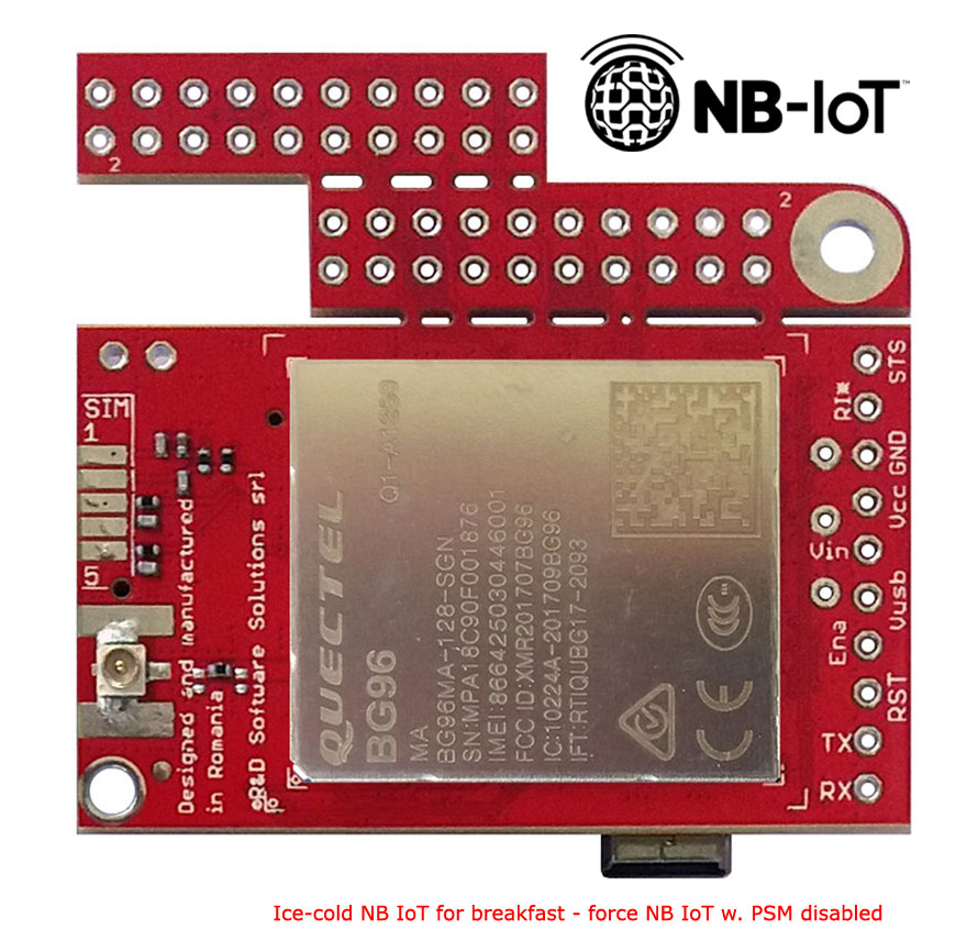
* Episode 2 - test the NB IoT network states BG96 detection (ACTIVE, IDLE and PSM - as in top-right image) and raw UDP data transmission.
* Episode 3 (this one) - force BG96 NB IoT in PSM disabled mode (BG96 used in permanent ACTIVE/IDLE mode).
Test environment: UDP RAW data transmission having one UDP echo server as remote endpoint (same as in Episode 2) and applying "disable PSM mode" settings on top.
* Episode 4 - how to upload sensors data using NB IoT UDP transmission to AllThingsTalk Cloud - soon available.
* Episode 5 ...TBD
Arduino support libraries and the source code used in this how to are available for download, for registered users, here: u-GSM downloads or xyz-mIoT downloads.
Required time: 5-15 minutes. The implementation time may vary depending on previous user experience.
Difficulty: beginner - intermediate.
Step 1 BG96 NB IoT Arduino classes install. Initial setup.
a. Replicate all steps described in NB IoT episode 1, step 1 (Arduino BG96 class download and install. Initial software setup).
b. In "itbp_modems_NBIoT_Class_example_UDP_echo.ino" [Arduino code example used in Episode 2] insert just under client.start() following line:
client.deactivatePSMmode();
b'. As an alternative: make a folder named "itbp_modems_NBIoT_Class_example_UDP_echo_PSM_disabled". Copy the code bellow, paste it one new file and save the file as "xyz_mIoT_NBIoT_Class_example_UDP_echo_PSM_disabled.ino" in the folder created in previous step.
itbp_modems_NBIoT_Class_example_UDP_echo_PSM_disabled.ino
| 1 | /* |
| 2 | itbp_modems_NBIoT_Class_example_UDP_echo_PSM_disabled.ino v 0.11/20190322 - BG96 NB IoT RAW UDP transmission having PSM mode disabled example |
| 3 | COPYRIGHT (c) 2015-2019 Dragos Iosub / R&D Software Solutions srl |
| 4 | |
| 5 | You are legaly entitled to use this SOFTWARE ONLY IN CONJUNCTION WITH xyz-mIOT by itbrainpower.net or u-GSM by itbrainpower.net DEVICES USAGE. Modifications, |
| 6 | derivates and redistribution of this software must include unmodified this COPYRIGHT NOTICE. You can redistribute this SOFTWARE and/or modify it under the |
| 7 | terms of this COPYRIGHT NOTICE. Any other usage may be permited only after written notice of Dragos Iosub / R&D Software Solutions srl. |
| 8 | |
| 9 | This SOFTWARE is distributed is provide "AS IS" in the hope that it will be useful, but WITHOUT ANY WARRANTY; without even the implied warranty of |
| 10 | MERCHANTABILITY or FITNESS FOR A PARTICULAR PURPOSE. |
| 11 | |
| 12 | Dragos Iosub, Bucharest 2019. |
| 13 | https://itbrainpower.net |
| 14 | */ |
| 15 | /*IMPORTANT NOTICE 0: install and run "udp_echo.py" listner on your server; write down, for use in step 4, the IP address and UDP listener PORT */ |
| 16 | /*IMPORTANT NOTICE 1: check itbpGSMdefinition.h for line 60&61 and set "__itbpModem__ xyzmIoT" or "__itbpModem__ uGSM"*/ |
| 17 | /*IMPORTANT NOTICE 2: check itbpGSMdefinition.h for line 64&65 and set "__Qmodule__ BC95G" or "__Qmodule__ BG96"*/ |
| 18 | /*IMPORTANT NOTICE 3: in itbpGPRSIPdefinition.h update your NB IoT "APN" and "numeric network id code" [Eg. Vodafone RO ==> 22601]*/ |
| 19 | /*IMPORTANT NOTICE 4: in itbpGPRSIPdefinition.h update your "SERVER_ADDRESS" and "SERVER_PORT", from step 0*/ |
| 20 | /*IMPORTANT NOTICE 5: in itbpGSMdefinition.h "itbpGSMClassDebug" and "atDebug" may help you....*/ |
| 21 | |
| 22 | #define DATAGRAMTOSEND "BG96/BG95G UDP test" //what you will send to the ECHO server |
| 23 | |
| 24 | /*REST cloud specific, more parameters in itbpGPRSIPdefinition.h*/ |
| 25 | int samplingPeriod = 120; //interval in seconds between transmissions... keep it > 60 sec [600 second to test some NB IoT signaling] |
| 26 | |
| 27 | char IMEI [16]; |
| 28 | |
| 29 | #include <itbpNBIoTClass_v0_3.h> |
| 30 | |
| 31 | #define DEBUG(x) {__itbpDebugPort__.print(millis());__itbpDebugPort__.print(" - ");__itbpDebugPort__.println(x);} |
| 32 | #define DEBUGP(x,y) {__itbpDebugPort__.print(millis());__itbpDebugPort__.print(" - ");__itbpDebugPort__.print(x);__itbpDebugPort__.println(y);} |
| 33 | |
| 34 | #if defined (__AVR_ATmega328P__) |
| 35 | int freeRam () { |
| 36 | extern int __heap_start, *__brkval; |
| 37 | int v; |
| 38 | return (int) &v - (__brkval == 0 ? (int) &__heap_start : (int) __brkval); |
| 39 | } |
| 40 | #endif |
| 41 | |
| 42 | // initialize the library instance |
| 43 | aGsmClient client; |
| 44 | |
| 45 | |
| 46 | |
| 47 | unsigned long startTime = 0; |
| 48 | |
| 49 | bool ledState = 0; |
| 50 | |
| 51 | |
| 52 | void setup(){ |
| 53 | #if (__itbpModem__ == xyzmIoT) |
| 54 | delay(10000); |
| 55 | #endif |
| 56 | |
| 57 | __itbpDebugPort__.begin(115200); //start debug port connection |
| 58 | //configure led |
| 59 | pinMode(LED_BUILTIN, OUTPUT); //embedded LED status indicator |
| 60 | digitalWrite(LED_BUILTIN, LOW); |
| 61 | ledState = 0; |
| 62 | |
| 63 | #if defined (__AVR_ATmega328P__) |
| 64 | DEBUGP(F("Free RAM: "), freeRam()); |
| 65 | #endif |
| 66 | |
| 67 | __itbpDebugPort__.println(F("Simple NBIoT UDP echo example...let's rock")); |
| 68 | __itbpDebugPort__.flush(); |
| 69 | |
| 70 | client.begin(); |
| 71 | client.deactivatePSMmode(); |
| 72 | |
| 73 | |
| 74 | |
| 75 | client.enableClockUpdate(1); //update available at next modem boot |
| 76 | |
| 77 | client.getIMEI(); //IMEI value in client.resp |
| 78 | memset(IMEI,0x00, sizeof(IMEI)); |
| 79 | strcpy(IMEI,client.resp); |
| 80 | DEBUGP(F("IMEI: "), IMEI); |
| 81 | |
| 82 | client.attachGPRS(); |
| 83 | |
| 84 | //let's verify the module date&time function |
| 85 | delay(1000); |
| 86 | client.getRTC(); |
| 87 | DEBUGP(F("time and date: "), client.resp); |
| 88 | |
| 89 | __itbpDebugPort__.println("connecting..."); |
| 90 | |
| 91 | //client.readServerDatagramReply(); |
| 92 | |
| 93 | startTime = millis() + (unsigned long)samplingPeriod*1000;//force send on the spot |
| 94 | } |
| 95 | |
| 96 | |
| 97 | |
| 98 | |
| 99 | void loop(){ |
| 100 | int res=0; |
| 101 | if (millis() - startTime < (unsigned long)samplingPeriod*1000){//waiting period |
| 102 | ledState = ! ledState; |
| 103 | if(ledState != 0) |
| 104 | digitalWrite(LED_BUILTIN, HIGH); |
| 105 | else |
| 106 | digitalWrite(LED_BUILTIN, LOW); |
| 107 | delay(500); |
| 108 | |
| 109 | }else{//start transmission |
| 110 | startTime = millis(); |
| 111 | digitalWrite(LED_BUILTIN, HIGH); //show sampling + uploadto cloud |
| 112 | |
| 113 | if (client.connected() || client.connect()){ |
| 114 | __itbpDebugPort__.println(F("send datagram")); |
| 115 | res = client.sendDatagram(DATAGRAMTOSEND); |
| 116 | if(res == 1){ |
| 117 | __itbpDebugPort__.println(F("wait 4 server reply...")); |
| 118 | unsigned long startlisten = millis(); |
| 119 | res = client.listenForNetworkSignaling(samplingPeriod, 1);//wait until receive server reply (samplingPeriod); //wait for server reply; res |
| 120 | if(res>0){ |
| 121 | __itbpDebugPort__.println(""); |
| 122 | __itbpDebugPort__.print(F("reply received>>")); |
| 123 | __itbpDebugPort__.print(client.resp); //server replied data in resp |
| 124 | __itbpDebugPort__.println(F("<<")); |
| 125 | //here wait for network signaling |
| 126 | res = client.listenForNetworkSignaling(samplingPeriod -(int)((millis()-startlisten)/1000), 4);//wait until enter PSM mode |
| 127 | } |
| 128 | else {//res <=0 |
| 129 | __itbpDebugPort__.print(F("ret value :")); |
| 130 | __itbpDebugPort__.println(res); |
| 131 | |
| 132 | } |
| 133 | /* |
| 134 | //other variant to send |
| 135 | res = client.listenForDatagramServerReply(samplingPeriod); //wait for server reply; res |
| 136 | if(res>0){ |
| 137 | __itbpDebugPort__.println(""); |
| 138 | __itbpDebugPort__.print(F("reply received>>")); |
| 139 | __itbpDebugPort__.print(client.resp); //server replied data in resp |
| 140 | __itbpDebugPort__.println(F("<<")); |
| 141 | //here wait for network signaling |
| 142 | //res = client.listenForNetworkSignaling(samplingPeriod - res, 4);//wait until ender PSM mode |
| 143 | } |
| 144 | */ |
| 145 | }else{//send datagram command report ERROR |
| 146 | __itbpDebugPort__.println(F("connectivity error...")); |
| 147 | } |
| 148 | }//end connect() |
| 149 | }//end tranmission |
| 150 | |
| 151 | } |
| 152 |
Step2 Arduino compile, upload and run the BG96 NB IoT having PSM mode disabled
Use Arduino[(arduino.cc v >= 1.8.5]
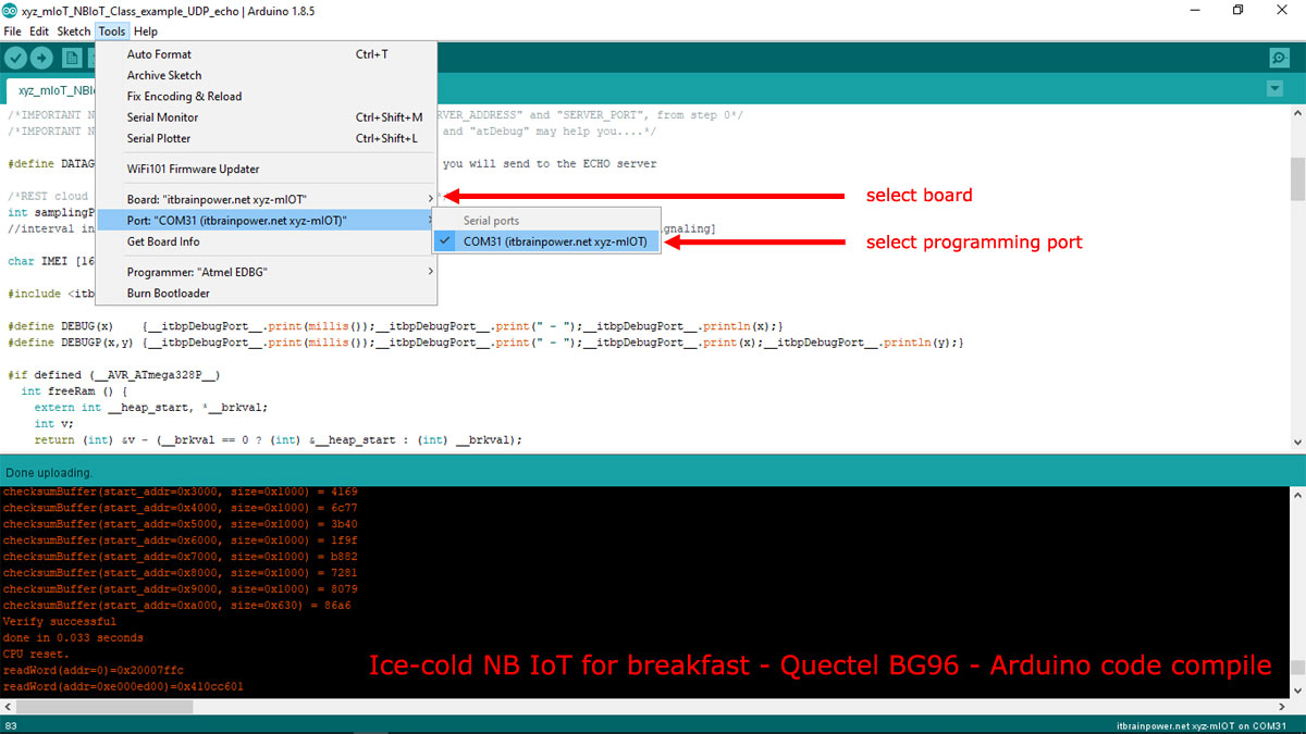
a. In Arduino, select board [Arduino Nano when run the test with u-GSM shield or xyz-mIoT shield] and the programming port [bellow, picture example for xyz-mIoT boards].

HINT [xyz-mIoT boards only]: In order to upload the code, you must press twice (fast) the xyz-mIoT shield RESET button [the board will switch into programming mode].
b. Compile and upload the code.
In order to visualize the debug output, use the Arduino Serial Monitor or other terminal by selecting the debug port with following settings: 115200bps, 8N, 1.
After sending and receiving data, the BG96 modem will NOT enter the PSM MODE. Compare test results with the one from Episode 2.
HINTS:
- in PSM mode, the BG96 "MODEM STATUS LED" is OFF.
- the "Arduino build in LED" (D13 led) signalize ACTIVE STATE being ON and PSM mode by blinking at ~2Hz.
ENJOY!
Well done, boys! Looks like we're have ice-cold sushi for breakfast!
TUTORIAL PROVIDED WITHOUT ANY WARRANTY!!! USE IT AT YOUR OWN RISK!!!!
