About episodes of this project
* Episode 1 - hardware setup required in order to run the software.
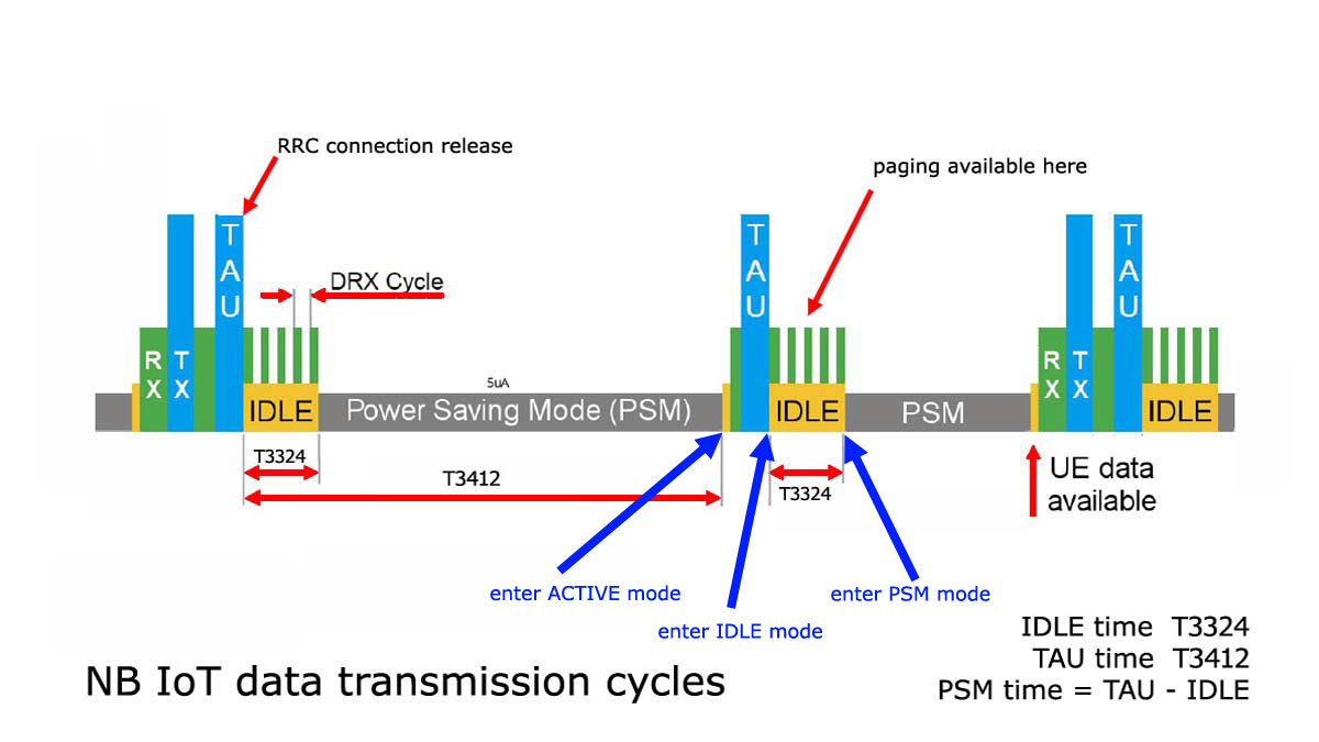
* Episode 2 (this one) - test the NB IoT network states BG96 detection (ACTIVE, IDLE and PSM - as in top-right image) and raw UDP data transmission.
* Episode 3 - force BG96 NB IoT in PSM disabled mode (BG96 used in permanent ACTIVE/IDLE mode - soon available.
* Episode 4 - how to upload sensors data using NB IoT UDP transmission to AllThingsTalk Cloud - soon available.
* Episode 5 ...TBD
Arduino support libraries and the source code used in this how to are available for download, for registered users, here: u-GSM downloads or xyz-mIoT downloads.
Required time: 10-15 minutes. The implementation time may vary depending on previous user experience.
Difficulty: beginner - intermediate.
Step 1 Arduino classes download. Software initial setup.
a. If you use u-GSM shield, just go to the next one. Download and install "xyz-mIoT shields Arduino class" from xyz-mIoT downlods. Class install directives can be found on dowload pages.
b. Download and install "NB IOT [UDP mode] support for u-GSM/xyz-mIoT shields" v0.3 or newer from xyz-mIoT downloads or u-GSM downloads. Install directives can be found on dowload pages.
c. Install and run "udp_echo.py" listner on your server (the code can be find also in "__UDP_listener_example" folder inside "NB IOT [UDP mode]" class); write down, for use in next steps, the IP address and UDP listener PORT.
d. Update some settings in h files inside "itbpNBIoTClass":
- "itbpGSMdefinition.h" goto lines 60&61 and choose from declaration __itbpModem__ xyzmIoT or __itbpModem__ uGSM
- "itbpGSMdefinition.h" goto lines 64&65 and select __Qmodule__ BG96"
- "itbpGPRSIPdefinition.h" - update the APN value, using the APN value of your NB IoT provider (Eg.: "nbiot.vodafone.ro" for Vodafone Romania)
- "itbpGPRSIPdefinition.h" - update the NETWORKID with numeric network id code for your NB IoT provider ("22601" for Vodafone Romania)
- "itbpGPRSIPdefinition.h" - update the LTE_BAND with numeric band code used for NB IoT service (LTE_B20 - LTE band B20 for Vodafone Romania). Take care here! There are two specific formats for this declaration - use the BG96 format!
- "itbpGPRSIPdefinition.h" - update the SERVER_ADDRESS and SERVER_PORT with values used for UDP echo listener service (from step c.)
e. Make a folder named "itbp_modems_NBIoT_Class_example_UDP_echo". Copy the code bellow, paste it one new file and save the file as "xyz_mIoT_NBIoT_Class_example_UDP_echo.ino" in the folder created in previous step.
itbp_modems_NBIoT_Class_example_UDP_echo.ino
| 1 | /* |
| 2 | itbp_modems_NBIoT_Class_example_UDP_echo.ino v 0.11/20190322 - UDP SEND RECEIVE SOFTWARE EXAMPLE |
| 3 | COPYRIGHT (c) 2015-2019 Dragos Iosub / R&D Software Solutions srl |
| 4 | |
| 5 | You are legaly entitled to use this SOFTWARE ONLY IN CONJUNCTION WITH xyz-mIOT by itbrainpower.net or u-GSM by itbrainpower.net DEVICES USAGE. Modifications, |
| 6 | derivates and redistribution of this software must include unmodified this COPYRIGHT NOTICE. You can redistribute this SOFTWARE and/or modify it under the |
| 7 | terms of this COPYRIGHT NOTICE. Any other usage may be permited only after written notice of Dragos Iosub / R&D Software Solutions srl. |
| 8 | |
| 9 | This SOFTWARE is distributed is provide "AS IS" in the hope that it will be useful, but WITHOUT ANY WARRANTY; without even the implied warranty of |
| 10 | MERCHANTABILITY or FITNESS FOR A PARTICULAR PURPOSE. |
| 11 | |
| 12 | Dragos Iosub, Bucharest 2019. |
| 13 | https://itbrainpower.net |
| 14 | */ |
| 15 | /*IMPORTANT NOTICE 0: install and run "udp_echo.py" listner on your server; write down, for use in step 4, the IP address and UDP listener PORT */ |
| 16 | /*IMPORTANT NOTICE 1: check itbpGSMdefinition.h for line 60&61 and set "__itbpModem__ xyzmIoT" or "__itbpModem__ uGSM"*/ |
| 17 | /*IMPORTANT NOTICE 2: check itbpGSMdefinition.h for line 64&65 and set "__Qmodule__ BC95G" or "__Qmodule__ BG96"*/ |
| 18 | /*IMPORTANT NOTICE 3: in itbpGPRSIPdefinition.h update your NB IoT "APN" and "numeric network id code" [Eg. Vodafone RO ==> 22601]*/ |
| 19 | /*IMPORTANT NOTICE 4: in itbpGPRSIPdefinition.h update your "SERVER_ADDRESS" and "SERVER_PORT", from step 0*/ |
| 20 | /*IMPORTANT NOTICE 5: in itbpGSMdefinition.h "itbpGSMClassDebug" and "atDebug" may help you....*/ |
| 21 | |
| 22 | #define DATAGRAMTOSEND "BG96/BG95G UDP test" //what you will send to the ECHO server |
| 23 | |
| 24 | /*REST cloud specific, more parameters in itbpGPRSIPdefinition.h*/ |
| 25 | int samplingPeriod = 300; //interval in seconds between transmissions... keep it > 60 sec [600 second to test some NB IoT signaling] |
| 26 | |
| 27 | char IMEI [16]; |
| 28 | |
| 29 | #include <itbpNBIoTClass_v0_3.h> |
| 30 | |
| 31 | #define DEBUG(x) {__itbpDebugPort__.print(millis());__itbpDebugPort__.print(" - ");__itbpDebugPort__.println(x);} |
| 32 | #define DEBUGP(x,y) {__itbpDebugPort__.print(millis());__itbpDebugPort__.print(" - ");__itbpDebugPort__.print(x);__itbpDebugPort__.println(y);} |
| 33 | |
| 34 | #if defined (__AVR_ATmega328P__) |
| 35 | int freeRam () { |
| 36 | extern int __heap_start, *__brkval; |
| 37 | int v; |
| 38 | return (int) &v - (__brkval == 0 ? (int) &__heap_start : (int) __brkval); |
| 39 | } |
| 40 | #endif |
| 41 | |
| 42 | // initialize the library instance |
| 43 | aGsmClient client; |
| 44 | |
| 45 | |
| 46 | |
| 47 | unsigned long startTime = 0; |
| 48 | |
| 49 | bool ledState = 0; |
| 50 | |
| 51 | |
| 52 | void setup(){ |
| 53 | #if (__itbpModem__ == xyzmIoT) |
| 54 | delay(10000); |
| 55 | #endif |
| 56 | |
| 57 | __itbpDebugPort__.begin(115200); //start debug port connection |
| 58 | //configure led |
| 59 | pinMode(LED_BUILTIN, OUTPUT); //embedded LED status indicator |
| 60 | digitalWrite(LED_BUILTIN, LOW); |
| 61 | ledState = 0; |
| 62 | |
| 63 | #if defined (__AVR_ATmega328P__) |
| 64 | DEBUGP(F("Free RAM: "), freeRam()); |
| 65 | #endif |
| 66 | |
| 67 | __itbpDebugPort__.println(F("Simple NBIoT UDP echo example...let's rock")); |
| 68 | __itbpDebugPort__.flush(); |
| 69 | |
| 70 | client.begin(); |
| 71 | |
| 72 | client.enableClockUpdate(1); //update available at next modem boot |
| 73 | |
| 74 | client.getIMEI(); //IMEI value in client.resp |
| 75 | memset(IMEI,0x00, sizeof(IMEI)); |
| 76 | strcpy(IMEI,client.resp); |
| 77 | DEBUGP(F("IMEI: "), IMEI); |
| 78 | |
| 79 | client.attachGPRS(); |
| 80 | |
| 81 | //let's verify the module date&time function |
| 82 | delay(1000); |
| 83 | client.getRTC(); |
| 84 | DEBUGP(F("time and date: "), client.resp); |
| 85 | |
| 86 | __itbpDebugPort__.println("connecting..."); |
| 87 | |
| 88 | //client.readServerDatagramReply(); |
| 89 | |
| 90 | startTime = millis() + (unsigned long)samplingPeriod*1000;//force send on the spot |
| 91 | } |
| 92 | |
| 93 | |
| 94 | |
| 95 | |
| 96 | void loop(){ |
| 97 | int res=0; |
| 98 | if (millis() - startTime < (unsigned long)samplingPeriod*1000){//waiting period |
| 99 | ledState = ! ledState; |
| 100 | if(ledState != 0) |
| 101 | digitalWrite(LED_BUILTIN, HIGH); |
| 102 | else |
| 103 | digitalWrite(LED_BUILTIN, LOW); |
| 104 | delay(500); |
| 105 | |
| 106 | }else{//start transmission |
| 107 | startTime = millis(); |
| 108 | digitalWrite(LED_BUILTIN, HIGH); //show sampling + uploadto cloud |
| 109 | |
| 110 | if (client.connected() || client.connect()){ |
| 111 | __itbpDebugPort__.println(F("send datagram")); |
| 112 | res = client.sendDatagram(DATAGRAMTOSEND); |
| 113 | if(res == 1){ |
| 114 | __itbpDebugPort__.println(F("wait 4 server reply...")); |
| 115 | unsigned long startlisten = millis(); |
| 116 | res = client.listenForNetworkSignaling(samplingPeriod, 1);//wait until receive server reply (samplingPeriod); //wait for server reply; res |
| 117 | if(res>0){ |
| 118 | __itbpDebugPort__.println(""); |
| 119 | __itbpDebugPort__.print(F("reply received>>")); |
| 120 | __itbpDebugPort__.print(client.resp); //server replied data in resp |
| 121 | __itbpDebugPort__.println(F("<<")); |
| 122 | //here wait for network signaling |
| 123 | res = client.listenForNetworkSignaling(samplingPeriod -(int)((millis()-startlisten)/1000), 4);//wait until enter PSM mode |
| 124 | } |
| 125 | /* |
| 126 | //other variant to send |
| 127 | res = client.listenForDatagramServerReply(samplingPeriod); //wait for server reply; res |
| 128 | if(res>0){ |
| 129 | __itbpDebugPort__.println(""); |
| 130 | __itbpDebugPort__.print(F("reply received>>")); |
| 131 | __itbpDebugPort__.print(client.resp); //server replied data in resp |
| 132 | __itbpDebugPort__.println(F("<<")); |
| 133 | //here wait for network signaling |
| 134 | //res = client.listenForNetworkSignaling(samplingPeriod - res, 4);//wait until ender PSM mode |
| 135 | } |
| 136 | */ |
| 137 | }else{//send datagram command report ERROR |
| 138 | __itbpDebugPort__.println(F("connectivity error...")); |
| 139 | } |
| 140 | }//end connect() |
| 141 | }//end tranmission |
| 142 | |
| 143 | } |
| 144 |
Alternate, you may start the "itbp_modems_NBIoT_Class_example_UDP_echo" example found in Arduino under "File/Examples/itbpNBIoTClass".
Step2 Arduino compile, upload and run the NB IoT echo test code
Open in Arduino[(arduino.cc v >= 1.8.5] the itbp_modems_NBIoT_Class_example_UDP_echo.ino project.
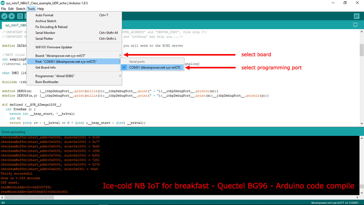
a. In Arduino, select board [Arduino Nano when run the test with u-GSM shield or xyz-mIoT shield] and the programming port [bellow, picture example for xyz-mIoT boards].

HINT [xyz-mIoT boards only]: In order to upload the code, you must press twice (fast) the xyz-mIoT shield RESET button [the board will switch into programming mode].
b. Compile and upload the code.
In order to visualize the debug output, use the Arduino Serial Monitor or other terminal by selecting the debug port with following settings: 115200bps, 8N, 1.
At registration phase, BG96 will aquire the NB IoT timers from the network. After sending and receiving data, the modem will enter PSM MODE when timer T3324 will expire. This cycle will repeat each 300sec. (data exchange rate set localy).
Data exchanged with the server, status switching between modes [switch to ACTIVE, IDLE and PSM modes] and "DATAGRAM received" event will be visualised in the debuging interface.
In PSM mode, the BG96 "MODEM STATUS LED" is OFF. Also, the "Arduino build in LED" (D13 led) will signalize ACTIVE (permanenty ON) / PSM mode (blink ~2Hz).
ENJOY!
Well done, boys! Looks like we're have ice-cold sushi for breakfast!
TUTORIAL PROVIDED WITHOUT ANY WARRANTY!!! USE IT AT YOUR OWN RISK!!!!

