About the project
Build your own IoT temperature logger with CLOUD data upload.
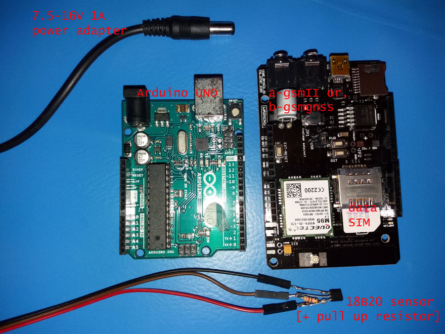
This project use for data transmission dual SIM full size GSM shield [a-gsmII], dual SIM full size GSM GNSS shield [b-gsmgnss] or our older a-gsm shield and Dallas/Maxim 18B20 1wire temperature sensor.
Required time: 30-45 minutes - hardware side and around 30-60 minutes software and cloud setup side.
Difficulty: beginner - intermediate.
IoT hardware bill of materials
- Arduino UNO
- a-gsmII v2.105 - Arduino GSM Shield [dual SIM, integrated antenna + uFL, quad band GSM/GPRS/DTMF/SMS] or
- b-gsmgnss v2.105 - Arduino GSM GPS Shield [dual SIM, integrated antenna + uFL, quad band GSM/GPRS/DTMF/SMS, Bluetooth 3.0, GNSS (GPS+GLONASS)] or
- old a-gsm shield
- 1WIRE temperature sensor(s) - I use DALLAS/MAXIM 18B20
- 8.2kb resistor
- 2G SIM card [having data plan enabled]
- some connecting wires
- 7.5-16V [12V recommended], 1A power source
CREDITS
Inside this project we used for 1WIRE temperature the "Dallas Temperature Control Library" developed by Miles Burton & Tim Newsome >> Arduino Library for Dallas Temperature ICs reference here. Thank you guys! Nice job!
About GSM shield used in this project
In this how to a-gsmII v2.105shield is used for representation. Same hardware settings applies for b-gsmgnss and a-gsm [for the last one differs only the SIM socket and voltage selector positioning].
More about shields:
a-gsmII documentation
b-gsmgnss documentation
a-gsm documentation
DALLAS/MAXIM 18B20 temperature sensor
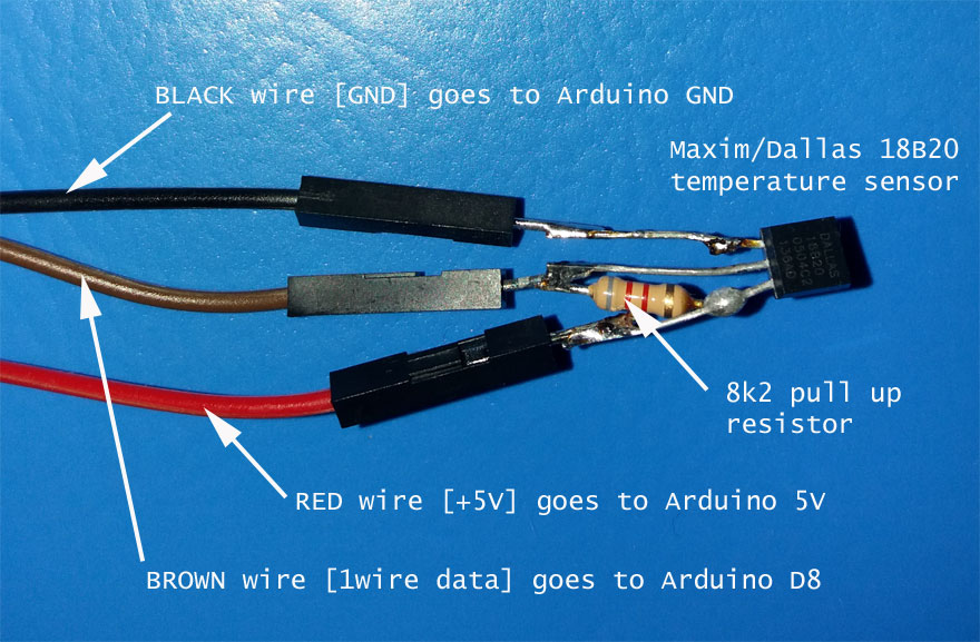
Solder the 8.2kb resistor between 18B20 Vdd pin(3)and 18B20 DQ pin(2). 18B20 Vdd pin(3) must be wired to Arduino 5V, 18B20 DQ pin(2) to Arduino D8 and 18B20 GND pin(1) to Arduino GND....see details bellow. DALLAS/MAXIM 18B20 reference here.
Hardware connections
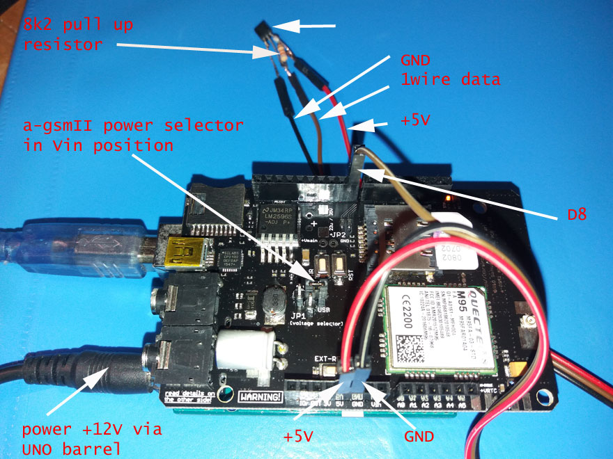
In the picture bellow all bundled together:
Hardware and wiring steps:
- solder the ARDUINO headers to a-gsmII shield
- plug-in [insert] the a-gsmII shield into Arduino UNO
- set the a-gsmII "Voltage selector" jumper in "Vin" position
- insert the SIM card in primary SIM socket [a-gsmII/b-gsmgnss - the SIM socket being in the proximity of the PCB; a-gsm - the SIM socket placed on TOP]. The SIM must have disabled the PIN checking proceedure [remove PIN check, here].
- Solder the 8k2 resistor to bw. 18B20 Vdd pin(3)and 18B20 DQ pin(2). Solder wires to 18B20 terminals.
- Wire 18B20 Vdd pin(3) to Arduino 5V, 18B20 DQ pin(2) to Arduino D8 and 18B20 GND pin(1) to Arduino GND.
- connect Arduino UNO USB to your PC
HINT:Multiple 1WIRE temperature sensors are required? Just connect them in paralel mode (single pull up resistor requiered... check for proper value...), hack the software (use 1,2.. sensorIndex in "sensors.getTempCByIndex(sensorIndex)" and multiple upload sessions) and define multiple token sensors in Cloud.
Software
a. Download the itbpGSMclass library [beta]:
"a-gsmII series software IoT REST support for ARDUINO" from a-gsmII download section,
or
"b-gsmgnss series software IoT REST support for ARDUINO" from b-gsmgnss download section, or
"a-gsm series software IoT REST support for ARDUINO" from a-gsm download section,
b. Uncompress the archive and install the class. In a nutshell, copy the the itbpGSMclass folder into your Arduino local user folder [mine is: "C:\Users\dragos\Documents\Arduino\libraries"] and restart Arduino environment. More detail about manual library installing, read Arduino library manual installation.
c. Make a folder named "agsmII_temperature_Robofun_cloud_logger".
d. Copy the code bellow, paste it one new file and save the file as "agsmII_temperature_Robofun_cloud_logger.ino" in the folder created in previous step. Alternate, you can
download from here (right click & save as):
agsmII_temperature_Robofun_cloud_logger.ino : ARDUINO THERMAL SMS ALARM & GSM/3G SHIELD - main code
agsmII_temperature_Robofun_cloud_logger.ino
| 1 | /* |
| 2 | agsmII_temp_Robofun_cloud_demo.ino v 0.2/20180302 - SOFTWARE EXAMPLE |
| 3 | COPYRIGHT (c) 2015-2018 Dragos Iosub / R&D Software Solutions srl |
| 4 | |
| 5 | You are legaly entitled to use this SOFTWARE ONLY IN CONJUNCTION WITH itbrainpower.net DEVICES USAGE. Modifications, derivates and redistribution |
| 6 | of this software must include unmodified this COPYRIGHT NOTICE. You can redistribute this SOFTWARE and/or modify it under the terms |
| 7 | of this COPYRIGHT NOTICE. Any other usage may be permited only after written notice of Dragos Iosub / R&D Software Solutions srl. |
| 8 | |
| 9 | This SOFTWARE is distributed is provide "AS IS" in the hope that it will be useful, but WITHOUT ANY WARRANTY; without even the implied |
| 10 | warranty of MERCHANTABILITY or FITNESS FOR A PARTICULAR PURPOSE. |
| 11 | |
| 12 | Dragos Iosub, Bucharest 2018. |
| 13 | http://itbrainpower.net |
| 14 | */ |
| 15 | |
| 16 | /*CLOUD specific info*/ |
| 17 | #define cloudURL "http://iot.robofun.ro/api/v1/senzor/" |
| 18 | #define sensorValURL "/input?value=" |
| 19 | #define tempToken "mvba9gs5fldntr5j85850of52f" //replace this with your temperature sensor token!!!! |
| 20 | //#define humiToken "mp67hppb262b832df1vecrsg5g" //replace this with your other sensor token, if any |
| 21 | /*CLOUD specific info*/ |
| 22 | |
| 23 | /* other settings, but very IMPORTANT*/ |
| 24 | //set SERVER_ADDRESS and SERVER_PORT in itbpGPRSIPdefinition.h Eg.: for ROBOFUN CLOUD [#define SERVER_ADDRESS "iot.robofun.ro" and #define SERVER_PORT "80" ] |
| 25 | //set APN, USERNAME and PASSWORD for your SIM card in itbpGPRSIPdefinition.h |
| 26 | //choose itbrainpower modem used in itbpGSMdefinition.h |
| 27 | /* other settings, but very IMPORTANT*/ |
| 28 | |
| 29 | int samplingPeriod = 60; //interval in seconds between scans... keep it > 60 sec |
| 30 | |
| 31 | /*local vars, sensors and actuators exchanged with the cloud*/ |
| 32 | //char dttime [31]; |
| 33 | //char IMEI [16]; |
| 34 | //int VBAT = 0; //value in milivolts |
| 35 | double temperature = 0; |
| 36 | /*local vars, sensors and actuators exchanged with the cloud*/ |
| 37 | |
| 38 | #include <itbpGSMClass.h> |
| 39 | |
| 40 | #define DEBUG(x) {__itbpDebugPort__.print(millis());__itbpDebugPort__.print(" - ");__itbpDebugPort__.println(x);} |
| 41 | #define DEBUGP(x,y) {__itbpDebugPort__.print(millis());__itbpDebugPort__.print(" - ");__itbpDebugPort__.print(x);__itbpDebugPort__.println(y);} |
| 42 | |
| 43 | #if (__itbpModem__ != xyzmIoT) |
| 44 | int freeRam () { |
| 45 | extern int __heap_start, *__brkval; |
| 46 | int v; |
| 47 | return (int) &v - (__brkval == 0 ? (int) &__heap_start : (int) __brkval); |
| 48 | } |
| 49 | #endif |
| 50 | |
| 51 | // initialize the library instance |
| 52 | aGsmClient client; |
| 53 | |
| 54 | /* sensor side here */ |
| 55 | #define ONE_WIRE_BUS 8 //Digital pin used for 1Wire temperature sensor reading |
| 56 | #include <OneWire.h> |
| 57 | #include <DallasTemperature.h> |
| 58 | |
| 59 | // Setup a oneWire instance to communicate with any OneWire devices |
| 60 | OneWire oneWire(ONE_WIRE_BUS); |
| 61 | // Pass our oneWire reference to Dallas Temperature. |
| 62 | DallasTemperature sensors(&oneWire); |
| 63 | /* sensor side here */ |
| 64 | |
| 65 | |
| 66 | unsigned long startTime = 0; |
| 67 | bool ledState = 0; |
| 68 | |
| 69 | /* |
| 70 | This function is CLOUD specific!!! Written for ROBOFUN CLOUD. |
| 71 | Function to parse the server responce |
| 72 | Vars: |
| 73 | timeout ==> int, timeout in seconds to wait for and parse the server responce |
| 74 | Returns: |
| 75 | 1 on success |
| 76 | 0 on error [found closed socket or PDP deactivation] |
| 77 | -1 on server timeout |
| 78 | */ |
| 79 | int readServerResponse(int timeout){ |
| 80 | |
| 81 | unsigned long startTime; |
| 82 | int ret =0; |
| 83 | startTime = millis(); |
| 84 | delay(10); |
| 85 | __itbpDebugPort__.println(F("start read...")); |
| 86 | while(true){ |
| 87 | client.readline(1000); |
| 88 | __itbpDebugPort__.println(client.resp);//just to see the server response |
| 89 | if (strstr(client.resp, "1;")) |
| 90 | { |
| 91 | __itbpDebugPort__.println(F("found confirmation...")); |
| 92 | ret = 1; |
| 93 | } |
| 94 | |
| 95 | if (strstr(client.resp, "0;")) |
| 96 | { |
| 97 | __itbpDebugPort__.println(F("error returned...")); |
| 98 | ret = -1; |
| 99 | } |
| 100 | |
| 101 | if (strstr(client.resp, sockDisconnected0)||strstr(client.resp, sockDisconnected1)||strstr(client.resp, sockDisconnected2)) |
| 102 | { |
| 103 | __itbpDebugPort__.println(F("sk disconnected...")); |
| 104 | client.stop(); //4 LTE and 3G |
| 105 | return ret; |
| 106 | }//sockDisconnected0 |
| 107 | |
| 108 | if(millis() - startTime > (unsigned long)timeout*1000 ) |
| 109 | { |
| 110 | __itbpDebugPort__.println(F("mark to...")); |
| 111 | client.stop(); //need to clean DATA interface and return the to AT command interface |
| 112 | return -2; |
| 113 | } |
| 114 | } |
| 115 | return -3;//never here |
| 116 | } |
| 117 | |
| 118 | /* |
| 119 | write data to the socket. |
| 120 | This function is CLOUD/protocol specific!!! This is written for ROBOFUN CLOUD. |
| 121 | Construct simple GET request. Eg.: "http://iot.robofun.ro/api/v1/senzor/rd53i6l1p02npjtv9971dab5jm/input?value=3.4" |
| 122 | */ |
| 123 | void sendGetRequest(char * sensorToken, double sensorData){ |
| 124 | String data; |
| 125 | data = String(cloudURL) + String(sensorToken) + String(sensorValURL) + String(sensorData); |
| 126 | __itbpDebugPort__.println(data); |
| 127 | |
| 128 | client.print("GET "); |
| 129 | client.print(data); |
| 130 | client.println(" HTTP/1.1"); |
| 131 | client.println(F("Host: " SERVER_ADDRESS)); |
| 132 | client.println(F("Connection: close")); |
| 133 | client.println(); |
| 134 | } |
| 135 | |
| 136 | |
| 137 | /* |
| 138 | simple function that send [and receive] data to [from] CLOUD |
| 139 | */ |
| 140 | |
| 141 | void sendData( void){ |
| 142 | //send temperture data |
| 143 | if (client.connected() || client.connect()){ |
| 144 | sendGetRequest(tempToken, temperature); |
| 145 | //client.println("\r\n"); |
| 146 | readServerResponse(SERVER_REPLY_TIMEOUT); |
| 147 | }else{ |
| 148 | __itbpDebugPort__.println(F("Socket/GPRS error...")); |
| 149 | } |
| 150 | /* |
| 151 | //send humidity data...or other sensor/token data |
| 152 | if (client.connected() || client.connect()){ |
| 153 | sendGetRequest(humiToken, humidity); |
| 154 | //client.println("\r\n"); |
| 155 | readServerResponse(SERVER_REPLY_TIMEOUT); |
| 156 | }else{ |
| 157 | __itbpDebugPort__.println(F("Socket/GPRS error...")); |
| 158 | } |
| 159 | */ |
| 160 | } |
| 161 | |
| 162 | |
| 163 | |
| 164 | void setup(){ |
| 165 | delay(10000); |
| 166 | __itbpDebugPort__.begin(115200); //start debug port connection |
| 167 | pinMode(13, OUTPUT); //configure the UNO D13 as output - UNO embedded LED used as ARMED/DISARMED status indicator |
| 168 | digitalWrite(13, LOW); |
| 169 | ledState = 0; |
| 170 | |
| 171 | /*sensor side*/ |
| 172 | sensors.begin(); //1Wire temperature sensor init |
| 173 | /*sensor side*/ |
| 174 | |
| 175 | |
| 176 | #if __itbpModem__ != xyzmIoT |
| 177 | DEBUGP(F("Free RAM: "), freeRam()); |
| 178 | #endif |
| 179 | __itbpDebugPort__.println(F("...let's rock")); |
| 180 | __itbpDebugPort__.flush(); |
| 181 | |
| 182 | client.begin(); |
| 183 | |
| 184 | client.enableClockUpdate(1); //update available at next GSM boot |
| 185 | |
| 186 | //client.getIMEI(); //IMEI value in client.resp |
| 187 | //memset(IMEI,0x00, sizeof(IMEI)); |
| 188 | //strcpy(IMEI,client.resp); |
| 189 | //DEBUGP(F("IMEI: "), IMEI); |
| 190 | |
| 191 | client.attachGPRS(); |
| 192 | __itbpDebugPort__.println("connecting..."); |
| 193 | |
| 194 | startTime = startTime + (unsigned long)samplingPeriod*1000;//force send on the spot |
| 195 | |
| 196 | } |
| 197 | |
| 198 | |
| 199 | |
| 200 | |
| 201 | void loop(){ |
| 202 | if (millis() - startTime < (unsigned long)samplingPeriod*1000){//waiting period |
| 203 | //__itbpDebugPort__.println(F("...")); |
| 204 | |
| 205 | ledState = ! ledState; |
| 206 | if(ledState != 0) |
| 207 | digitalWrite(13, HIGH); |
| 208 | else |
| 209 | digitalWrite(13, LOW); |
| 210 | delay(500); |
| 211 | } |
| 212 | else{ |
| 213 | startTime = millis(); |
| 214 | digitalWrite(13, HIGH); //show sampling + uploadto cloud |
| 215 | |
| 216 | __itbpDebugPort__.println(F("")); |
| 217 | |
| 218 | sensors.requestTemperatures(); |
| 219 | temperature = (double)sensors.getTempCByIndex(0); |
| 220 | |
| 221 | //temperature = 100*(rand() % 100); |
| 222 | DEBUGP(F("Temp: "),temperature); |
| 223 | |
| 224 | if (!client.connected()) client.transparent(); //switch to transparent socket mode, if available |
| 225 | |
| 226 | DEBUG(F("send sensors start")); |
| 227 | sendData(); //push sensors to the cloud |
| 228 | DEBUG(F("send sensors stop")); |
| 229 | |
| 230 | digitalWrite(13, LOW); //show sampling + uploadto cloud |
| 231 | ledState = 0; |
| 232 | } |
| 233 | } |
| 234 |
e. Parameters/variables to be set in "agsmII_temperature_Robofun_cloud_logger.ino":
- tempToken [line 19] - replace with sensor token generated on Robofun cloud [see next chapter]
- samplingPeriod [line 29]
f. Parameters/variables to be set in "itbpGSMclass library":
- set SERVER_ADDRESS and SERVER_PORT in itbpGPRSIPdefinition.h for ROBOFUN CLOUD
#define SERVER_ADDRESS "iot.robofun.ro"
#define SERVER_PORT "80"
- set APN, USERNAME and PASSWORD for your SIM card in itbpGPRSIPdefinition.h
- choose itbrainpower modem used in itbpGSMdefinition.h, in this example:
#define __itbpModem__ agsmII
- also, good to know >> itbpGSMClassDebug, atDebug on / off and MAX_BUFFER_SIZE... in itbpGSMdefinition.h
Robofun cloud. Define new sensor. Copy TOKEN data
Open https://iot.robofun.ro.
Create new account.
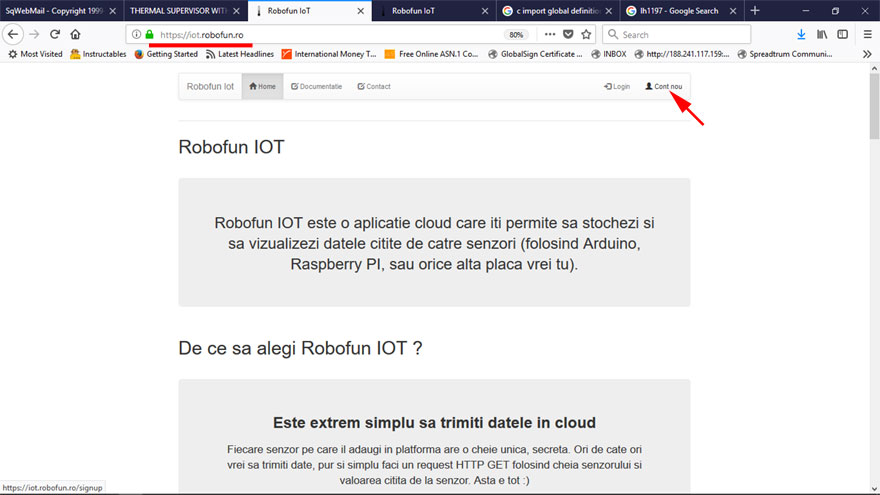
Create new sensor.
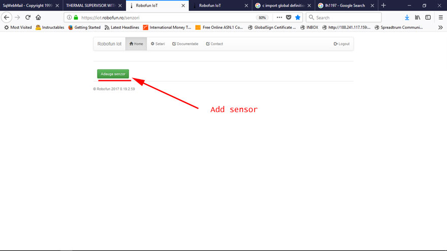
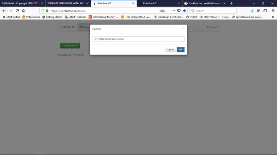
Scroll down the page until "TOKEN" chapter.
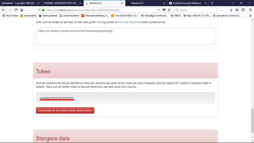
Copy your sensor TOKEN id [up-here underlined with RED].
Use this value for tempToken [line 19 in "agsmII_temperature_Robofun_cloud_logger.ino"]
Robofun cloud. Visualize temperature log record
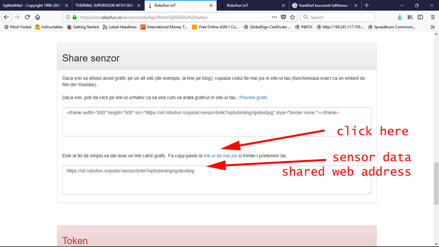
The temperature logged data can be visualized in Robofun cloud sensor page or, in public (shared) page. To do this,
scroll up the page until "Share senzor" chapter, copy the public link or iframe (see bellow picture).
TUTORIAL PROVIDED WITHOUT ANY WARRANTY!!! USE IT AT YOUR OWN RISK!!!!
