The purpose of this howto it is to show to you how to connect standard PC audio headsets (or equivalent audio periferals) port to your c-uGSM / h-nanoGSM shield.
You can use any capacitor microphone and 8-32ohm speaker with your c-uGSM / h-nanoGSM shields connecting (solder) them directly to the ANALOG AUDIO port (see into the page bottom), but now the new f-Audio adapter provides an elegant alternative.
What you will need
- f-AudioOutputs adapter bundle v1.02 1 pcs.
- 1 x 6 0.1" (2.54mm) standard pin-header
- 1 x 6 0.1" (2.54mm) standard socket-header (1 pcs.)
- c-uGSM shield (micro) v1.13 1 pcs, or
- h-nanoGSM shield (nano) v1.08 1 pcs.
- soldering tool, solder wire, clip/pinch, cutter pliers.
General considerations, conventions and references
Hardware references
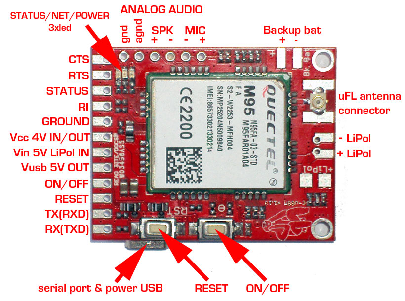
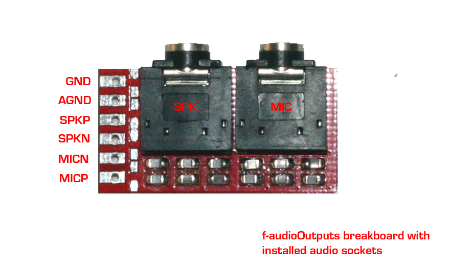
GSM SHIELD (micro) c-uGSM v 1.13 top PCB view f-AudioOutputs v 1.02 top PCB view (w. installed audio sockets)


In the top PCB side, left hand, enumerating from left to right:
1. GND * GSM SHIELD DIGITAL GROUND
2. AGND * GSM SHIELD ANALOG GROUND
3. SPK+ * GSM SHIELD positive SPEAKER OUT
4. SPK- * GSM SHIELD negative SPEAKER OUT
5. MIC- * GSM SHIELD negative MICROPHONE IN
6. MIC+ * GSM SHIELD positive MICROPHONE IN
In the left PCB side, enumerating from top to bottom:
1. GND * AUDIO ADAPTER DIGITAL GROUND
2. AGND * AUDIO ADAPTER ANALOG GROUND
3. SPKP * AUDIO ADAPTER positive SPEAKER OUT
4. SPKN * AUDIO ADAPTER negative SPEAKER OUT
5. MICN * AUDIO ADAPTER negative MICROPHONE IN
6. MICP * AUDIO ADAPTER positive MICROPHONE IN
GSM SHIELD (nano) h-nanoGSM v 1.08 top PCB view
In the top PCB side, left hand, enumerating from left to right:
1. GND * GSM SHIELD DIGITAL GROUND
2. AGND * GSM SHIELD ANALOG GROUND
3. SPK+ * GSM SHIELD positive SPEAKER OUT
4. SPK- * GSM SHIELD negative SPEAKER OUT
5. MIC- * GSM SHIELD negative MICROPHONE IN
6. MIC+ * GSM SHIELD positive MICROPHONE IN
f-AudioOutputs SPEAKER and MICROPHONE jacks howto wire
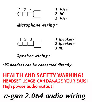
The f-AudioOutputs SPEAKER and MICROPHONE connections are full equivalent with the one implementated in the a-gsm shield.

 SPEAKER and MICROPHONE connections should be done as in above-left picture.
HEALTH and SAFETY WARNING!
The c-uGSM shield have HIGH POWER AUDIO output (up to 870mW)! HEADSET USAGE CAN DAMAGE YOUR EARS (direct connection or trough f-AudioOutputs adapter)!
Brief c-uGSM direct (w/o f-AudioOutputs adapter)audio hardware connectivity description
1. c-uGSM SPK+ and SPK- goes to the speaker (respect the polarity),
2. c-uGSM MIC+ and MIC- goes to the microphone (respect the polarity),
3. c-uGSM GND and AGND must be connected together
The speaker must have 32 ohm (recommended) and the microphone must be capacitive.
For the h-nanoGSM shield, the very same wirring may be applied.