Pin to pin compatible, compact and light weight modules and having embedded USB ports, c-uGSM and d-u3G shields (micro) are our latest GSM / 3G-UMTS shields compatible with Arduino, Raspeberry PI, Raspberry PI or with any other 2.8-5V micro-controller board.
Next, you will learn how to start using them.
What you will need
- c-uGSM shield (micro) v1.13 1 pcs. or
- d-u3G shield (micro) v1.13 1 pcs.
- GSM (2G) SIM card, for c-uGSM or 3G SIM card, for d-u3G 1 pcs
- SMA GSM/3G antenna and uFL to SMA pigtail (only for uFL versions)
- JST TH 2 pin connector and (200mAh->2000mAh) LiPOL battery (only if you intend to use the shield in LiPOL battery configuration)
- 0.1" (2.54mm) standard pin headers (13x for d-u3G / 12x for c-uGSM)
- 0.1" (2.54mm) standard jumper (1 pcs.)
- USB cables and connection wires
- soldering tool, solder wire, clip/pinch
General considerations, conventions and references
Hardware references
GSM SHIELD (micro) c-uGSM v 1.13 top PCB view 3G SHIELD (micro) d-u3G v 1.13 top PCB view

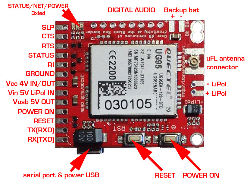
In the left edge of the top PCB side, bottom to top:
1. RX(TXD) - GSM SHIELD SERIAL RX (TXD) - input
2. TX(RXD) - GSM SHIELD SERIAL TX (RXD) - output
3. RESET - GSM SHIELD RESET - input, active LOW*
4. ON/OFF - GSM SHIELD POWER ON/OFF - input, active LOW*
5. Vusb - POWER PIN - output +5V (USB +5V)
6. Vin - POWER PIN - input +5V for LiPol charger only
7. Vcc - POWER PIN - input/output +4V**
8. GND - POWER and DIGITAL GROUND
9. RI - GSM SHIELD RING INDICATOR - output
10. STATUS - GSM SHIELD STATUS - output
11. RTS - GSM SHIELD READY TO SEND - output
12. CTS - CLEAR TO SEND - input
* min. 200msec. pulse
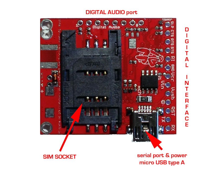
In the left edge of the top PCB side, bottom to top: 1. RX(TXD) - 3G SHIELD SERIAL RX (TXD) - input
2. TX(RXD) - 3G SHIELD SERIAL TX (RXD) - output
3. RESET - 3G SHIELD RESET - input, active HIGH*
4. POWER ON - 3G SHIELD POWER ON - input, active HIGH*
5. Vusb - POWER PIN - output +5V (USB +5V)
6. Vin - POWER PIN - input +5V for LiPol charger only
7. Vcc - POWER PIN - input/output +4V**
8. GND - POWER and DIGITAL GROUND
9. RI - 3G SHIELD RING INDICATOR - output
10. STATUS - 3G SHIELD STATUS - output
11. RTS - 3G SHIELD READY TO SEND - output
12. CTS - CLEAR TO SEND - input
13. SLP - SLEAP - input, active HIGH
* min. 200msec. pulse
The only hardware difference on "POWERING, SERIAL and CONTROL INTERFACE", between c-uGSM and d-u3G, is that SLP-SLEEP pin on c-uGSM it is not implemented / present (do not connect this). Differences between START/STOP and RESET logical procedures are fixed in Arduino C and Raspberry PI Python software (see examples). Just ignore them.
As general approach, you CAN replace c-uGSM with d-u3G and in reverse mode as simple as: switch the one board with an other (with respect to the correspondent pins) and re-compile/run the code using appropriate libraries/functions.
GSM SHIELD (micro) c-uGSM v 1.13 bottom PCB view 3G SHIELD (micro) d-u3G v 1.13 bottom PCB view

The drawings uphere may be used as general wiring guidelines, but in order to chose your final configuration you must read the sections bellow.
USB communication support, drivers reference
On both c-uGSM and d-u3G shields, the USB port CAN BE used for powering and communication. The USB communication for both modules it is natively supported by Raspberry PI and Raspberry PI2 on Raspian OS. The Raspian OS will recognize the USB serial port as /dev/TTYUSB0 for c-uGSM shield and as /dev/ttyACM0 for d-u3G shield. As backup, if something goes wrong, you can still use the 2015-02-16 version, used by us for testing.
You can download it from here:
http://itbrainpower.net/a-gsm/downloadables/2015-02-16-raspbian-wheezy.zip .
Download the c-uGSM (CP2102) USB drivers from Silicon Labs site
Download the d-u3G shield USB Windows driver
Wiring conventions used in this document, seen by the c-uGSM / d-u3G shield
YELLOW wire - RX(TXD)
GREEN wire - TX(RXD)
BLUE wire - RESET
VIOLET wire - POWER ON/OFF (c-uGSM) or POWER ON (d-u3G)
RED wire - Vin (5V IN LiPOL IN) - used only in LiPOL configurations powered from external 5V source as our g-SPS LiPOL.
GREY wire - Vcc (4V IN/OUT) - used only in WITOUT LiPOL configurations. Must be connected to external 4V source as our g-SPS DDRV.
BROWN wire - GND(GROUND)
ORANGE wire - STS(STATUS)
display/hide advanced interfacing and wiring info