The main purpose of this howto it is to guide you to make a convenient and elegant connection (no more wires), using i-hatGSM3G - RASPBERRY PI adapter, between the RPI (like) boards and c-uGSM / d-u3G / h-nanoGSM shields .
The second purpose is to show a way of powering the RPi boards, using same principle presented in RASPBERRY PI FREE STYLE POWERING, but more convenient (no more wires) using our i-hatGSM3G - RASPBERRY PI adapter board, in conjunction with g-SPS 5V version[LiPOL] switching power supply board.
What you will need
- i-hatGSM3G RPi adapter bundle v1.01(*) 1 pcs.
- additional 1 x 10 0.1" (2.54mm) standard pin-header 1/2pcs., depending on integration level you decide to go to
- additional 1 x 10 0.1" (2.54mm) standard socket-header (same as above)
- g-SPS v1.02 - 4V [DDRV] or g-SPS v1.02 - 5V [LiPOL] - switching power supplies 1 pcs (not mandatory for all examples).
- l-LTE 4G/LTE +GNSS shield v1.07 [3G/LTE + GNSS modular modem] 1 pcs. or
- d-u3G shield (micro) v1.13 [3G/UMTS modular modem] 1 pcs. or
- c-uGSM shield (micro) v1.13 [DUAL SIM GSM(2G) modular modem] 1 pcs. or
- h-nanoGSM shield (micro) v1.08 [GSM + BTH 3.0 modular modem] 1 pcs.
- Raspberry PI board (3, 2, Zero, B+)(**) or Raspberry PI like board (BeagleBone, BananaPi, other)(***)
- soldering tool, solder wire, clip/pinch, cutter pliers.
* the i-hatGSM3G101B bundle contains: 2.54 mm(0.1") 2x10 pin-header socket 1pcs., 2.54 mm(0.1") 1x10 pin-header socket 1pcs. and i-hatGSM3G RPi HAT adapter board 1pcs.
** we performed our tests using Raspberry PI 3, Raspberry PI 2 and Raspberry PI B+. Most pictures includes Raspberry PI 3.
*** double check the efective GPIO expansion map available on your device.
General considerations, conventions and references
l-LTE, d-u3G, c-uGSM and h-nanoGSM modular modem shields hardware references
Read about: l-LTE, d-u3G, c-uGSM and h-nanoGSM modular modem shields howto start tutorial
g-SPS 4V version [DDRV] and g-SPS 5V version [LiPOL] switching power supplies hardware references
Read about: g-SPS 4V version [DDRV] and g-SPS 5V version [LiPOL] switching power supplies
i-hatGSM3G Raspberry PI adapter hardware references
Just to make the long story short: the i-hatGSM3G adapter implements, without wires, the raspberry PI conection references bellow:
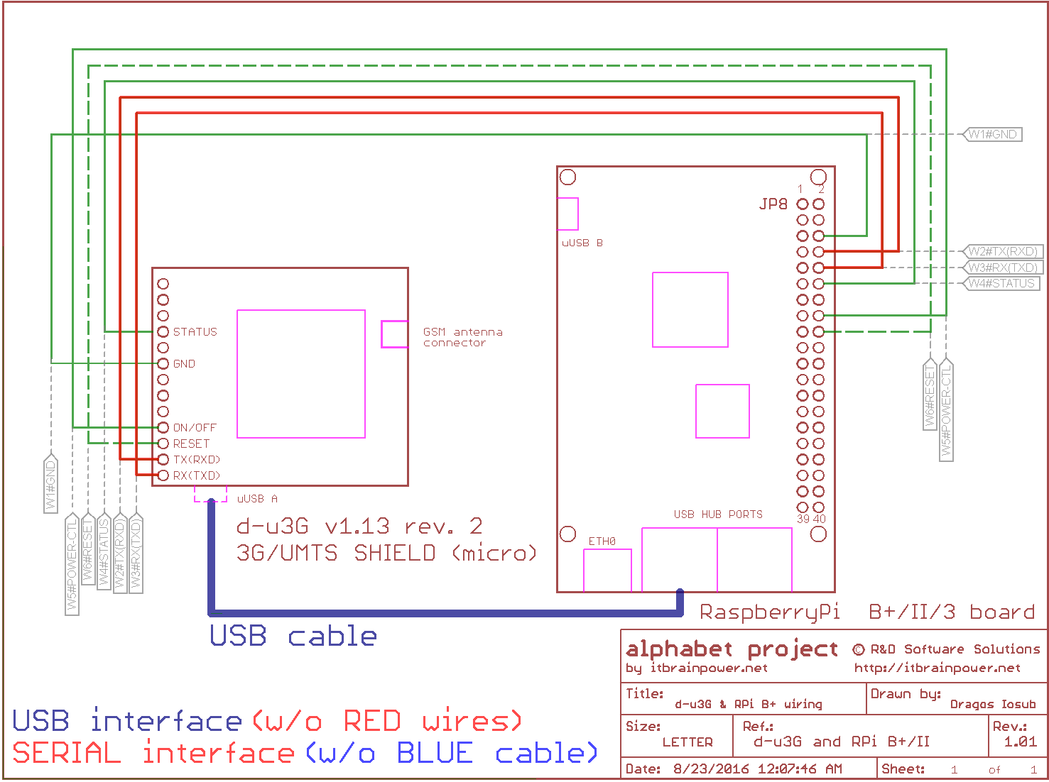
c-uGSM SHIELD to Raspberry PI wiring reference d-u3G SHIELD to Raspberry PI wiring reference

i-hatGSM3G Raspberry PI adapter board and options brief presentation

Observe the solder jumpers, in picture up-here:
- JP1 - circuit between 5V POWER between RPi +5V pin and Vin (5V on GSM/3G connector) - CIRCUIT OPEN (not connected) default
- JP2 - RX connection - CIRCUIT CLOSED (connected) default
- JP3 - TX connection - CIRCUIT CLOSED (connected) default
- JP4 - circuit between RPi pin18 and RST (RESET on GSM/3G connector) - CIRCUIT OPEN (not connected) default
HINTS:
- DO NOT MODIFY SOLDER JUMPERS CONFIGURATION UNTIL YOU REALLY KNOW WHAT YOU ARE DOING!
- SPECIAL WARNING FOR JP1! WRONG CONFIGURATION MAY DAMAGE YOUR Raspberry PI and/or g-SPS power supply and/or 3G/GSM shield!