The main purpose of this howto it is to guide you to make a convenient and elegant connection (no more wires), using the j-328GSM3GLader Arduino Pro Mini adapter board, between the Adruino Pro Mini (like) boards and c-uGSM / d-u3G / h-nanoGSM shields....you can use this bundle as: programmable GSM interface, mobile IoT hardware interface (access sensor data remotely, or control actuators), SMS / GPRS / DTMF automation platform ...
What you will need
- j-328GSM3GLader Arduino Pro Mini adapter board v1.02(*) 1 pcs.
- g-SPS v1.02 - 4V [DDRV] or g-SPS v1.02 - 5V [LiPOL] - switching power supplies 1 pcs (not mandatory for all examples).
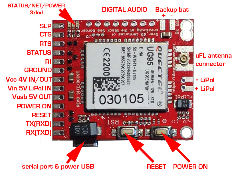
- c-uGSM shield (micro) v1.13 1 pcs. or
- d-u3G shield (micro) v1.13 1 pcs. or
- h-nanoGSM shield (micro) v1.08 1 pcs.
- Arduino Pro Mini board (**) or Arduino Pro Mini like boards [Arduino Micro, Arduino Nano USB, ArduinoPro Mini, Atmega32U4 based Fio board, a-star mini(no GND connection), Arduino Yun Mini, Metro Mini 328(no GND connection), Pro Trinket(no GND connection), RedStick, other mini-boards] (***)
- Additional 1 x 2 0.1" (2.54mm) standard pin header straight or 90 degree (optional),
- soldering tool, solder wire, clip/pinch, cutter pliers.
* the j328GSM3GLader102B bundle contains: 2.54 mm(0.1") 1x10 pin-header socket 1pcs., 2.54 mm(0.1") 1x8 pin-header socket 1pcs. and j-328GSM3GLader Arduino Pro Mini adapter board 1pcs.
** we performed our tests using Arduino Pro Mini clone board and other boards. Most pictures includes Arduino Pro Mini clone board.
*** double check the efective GPIO expansion map available on your device. The compatibility "golden rule": check your u-controller board for pinout organized in the following row order GND, D2, D3, D4, D5, D6 and D7 (D4 not used, GND not mandatory >> check bellow for "NO GND workaround").
General considerations, conventions and references
j-328GSM3GLader Arduino Pro Mini adapter board hardware references
Just to make the long story short: the j-GSM3GLAder adapter connects, without wires, the Arduino Pro Mini (like) boards with our GSM / 3G or LTE modular shields. See bellow:

c-uGSM shield, d-u3G shield and h-nanoGSM shield hardware references
The c-uGSM and d-u3G shields are pin to pin compatible with each other. The c-uGSM is quad band (worldwide compatible) and has support for 2x SIM cards. The other unit, d-u3G, uses a single 3G SIM (3G only the North American version; 3G+GSM the European and rest of the world version).
GSM SHIELD (micro) c-uGSM v 1.13 top PCB view 3G SHIELD (micro) d-u3G v 1.13 top PCB view

GSM SHIELD (nano) h-nanoGSM v 1.08 top PCB view

h-nanoGSM - quad band GSM only (+ Bluetooth 3.0)and is worldwide compatible - nano shield is packed in an compact format 1.25.x1.16.(31.759.46mm) and weighs around 8g. The h-nanoGSM has the same functionality as its bigger brothers (c-uGSM and d-u3G), and is not only a breakout board, but a full shield with powerful embedded features including USB support (communication and powering), auto power level 2.8V-5V digital interfaces and an integrated LiPo battery charger.
Read more about: c-uGSM shield, d-u3G shield and h-nanoGSM shield howto start tutorial
g-SPS 4V version [DDRV] and g-SPS 5V version [LiPOL] switching power supplies hardware references
Both the g-SPS 4V [DDRV] and g-SPS 5V [LiPOL] switching power supplies mentioned in the parts list are modular, designed for pin to pin compatibility with itbrainpower.net.s family of modems. The first one (g-SPS 1.02 . 4V [DDRV]) is used as power supply adapter for the c-uGSM / d-u3G / h-nanoGSM shields in configurations without a Lithium Polymer battery. The second one (g-SPS 1.02 . 5V [LiPOL]) is used in configurations with a Lithium Polymer battery connected to the shield, when the main power source has a voltage above 5V (6-20V).
Read about: g-SPS 4V version [DDRV] and g-SPS 5V version [LiPOL] switching power supplies
Arduino Pro Mini hardware references
Read about: Arduino Pro Mini For other compatible boards...use google to find proper hardware references.
Hint: No matter what Arduino Pro Mini version you use (3.3V or 5V), you don't need to bother with the logical levels interfacing! All our modems (c-uGSM, h-nanoGSM and d-u3G) automatically handles the logical interfacing.
j-328GSM3GLader Arduino Pro Mini adapter board brief introduction
To make the long story short, the j-GSM3GLAder adapter allows you to directly connect the Arduino Pro Mini (like) boards with itbrainpower.net modular GSM / 3G or (near future) LTE modem shields, saving space(no wirings) and also the assembly time.


In the pictures up-here, observe the GSM/3G and the 328(u-controller) sides marking on the BOTTOM face. Also,
observe the solder jumpers (plaaced on the BOTTOM face):
- JP1 - GND - CIRCUIT CLOSED (connected) default WATCH OUT when NO GROUND u-controller board it is used! Read about "NO GND workaround" bellow.
- JP2 - circuit between Vcon POWER on "POWER SIDE SECTION" and Vin (5V on GSM/3G connector) - CIRCUIT OPEN (not connected) default
HINTS:
- DO NOT MODIFY SOLDER JUMPERS CONFIGURATION UNTIL YOU REALLY KNOW WHAT YOU ARE DOING!
SPECIAL WARNINGS FOR JP1 and JP2! WRONG CONFIGURATION MAY DAMAGE YOUR Arduino Pro Mini (like) board and/or g-SPS power supply and/or 3G/GSM shield!