itbrainpower.net
|
||||||||||||||||||||||||||||||||||||||||||||||||||||||||
c-uGSM - GSM shield (micro) :: FEATURES AT A GLANCE:
Quad band GSM/GPRS module (Quectel M95F) with true worldwide coverage: 850MHz, 900MHz, 1800MHz and 1900MHz. |
||||||||||||||||||||||||||||||||||||||||||||||||||||||||
c-uGSM - GSM shield (micro) :: INTERFACES, SWITCHES and CONNECTORS
 - top interface description :: CLICK TO SEE FULL SIZE IMAGE") GSM SHIELD (micro) c-uGSM v 1.13 top PCB view - bottom interface description :: CLICK TO SEE FULL SIZE IMAGE")
GSM SHIELD (micro) c-uGSM v 1.13 bottom PCB viewGSM SHIELD POWERING, SERIAL and CONTROL INTERFACEIn the left edge of the top PCB side, bottom to top:1. RX(TXD) - modem TX - output 2. TX(RXD) - modem RX - input 3. RESET - GSM SHIELD RESET - input, active LOW* 4. ON/OFF - GSM SHIELD POWER ON/OFF - input, active LOW* 5. Vusb - POWER PIN - output +5V (USB +5V) 6. Vin - POWER PIN - input +5V for LiPol charger only 7. Vcc - POWER PIN - input/output +4V** 8. GND - POWER and DIGITAL GROUND 9. RI - GSM SHIELD RING INDICATOR - output 10. STATUS - GSM SHIELD STATUS - output 11. RTS - GSM SHIELD READY TO SEND - output 12. CTS - CLEAR TO SEND - input * min. 200msec. pulse GSM SHIELD BATTERY and ANTENNAIn the right edge of the top PCB side, bottom to top:1. + LiPol - connect + pole of the LiPol battery 2. + LiPol - connect - pole of the LiPol battery 3. GSM antenna connector - uFL or SMA F GSM SHIELD AUDIO INTERFACE** and BACKUP BATTERYIn the top edge of the top PCB side, left to right:1. GND - GND connection for analog audio 2. AGND - Analog GND for analog audio 3. SPK+/SPKP - loudspeaker output + pole** 4. SPK-/SPKN - loudspeaker output - pole** 5. MIC-/MICN - cap. microphone input - pole 6. MIC+/MICP - cap. microphone input + pole 7. BkBat+ : Backup battery + pole*** 8. BkBat- : Backup battery - pole ** WARNING! The HIGH POWER AUDIO output may drive up to 600mW RMS! Headset usage can damage your ears! *** WARNING! For non rechargeable battery (eg. Silver Oxide coin cell): insert one diode (1N4148) between the battery plus pole and the GSM shield "BkBat+" pad. 1N4148 anode must be connected with the battery. GSM SHIELD SWITCHESIn the bottom edge of the top PCB side, left to right:1. RESET - GSM SHIELD RESET 2. ON/OFF - GSM SHIELD TOGGLE POWER GSM SHIELD DUAL SIM SOCKET AND USB PORTIn the bottom PCB side, left to right:1. DUAL SIM SOCKET - SIM0 (default SIM) placed underneath (in the very proximity of the PCB) and SIM1 (secondary SIM) placed above SIM0 2. USB PORT - micro USB type A - GSM SHIELD POWERING and SERIAL to USB bridge adapter |
||||||||||||||||||||||||||||||||||||||||||||||||||||||||
| | ||||||||||||||||||||||||||||||||||||||||||||||||||||||||
c-uGSM - GSM shield (micro) :: Arduino /Raspberry PI logical interfacing |
||||||||||||||||||||||||||||||||||||||||||||||||||||||||
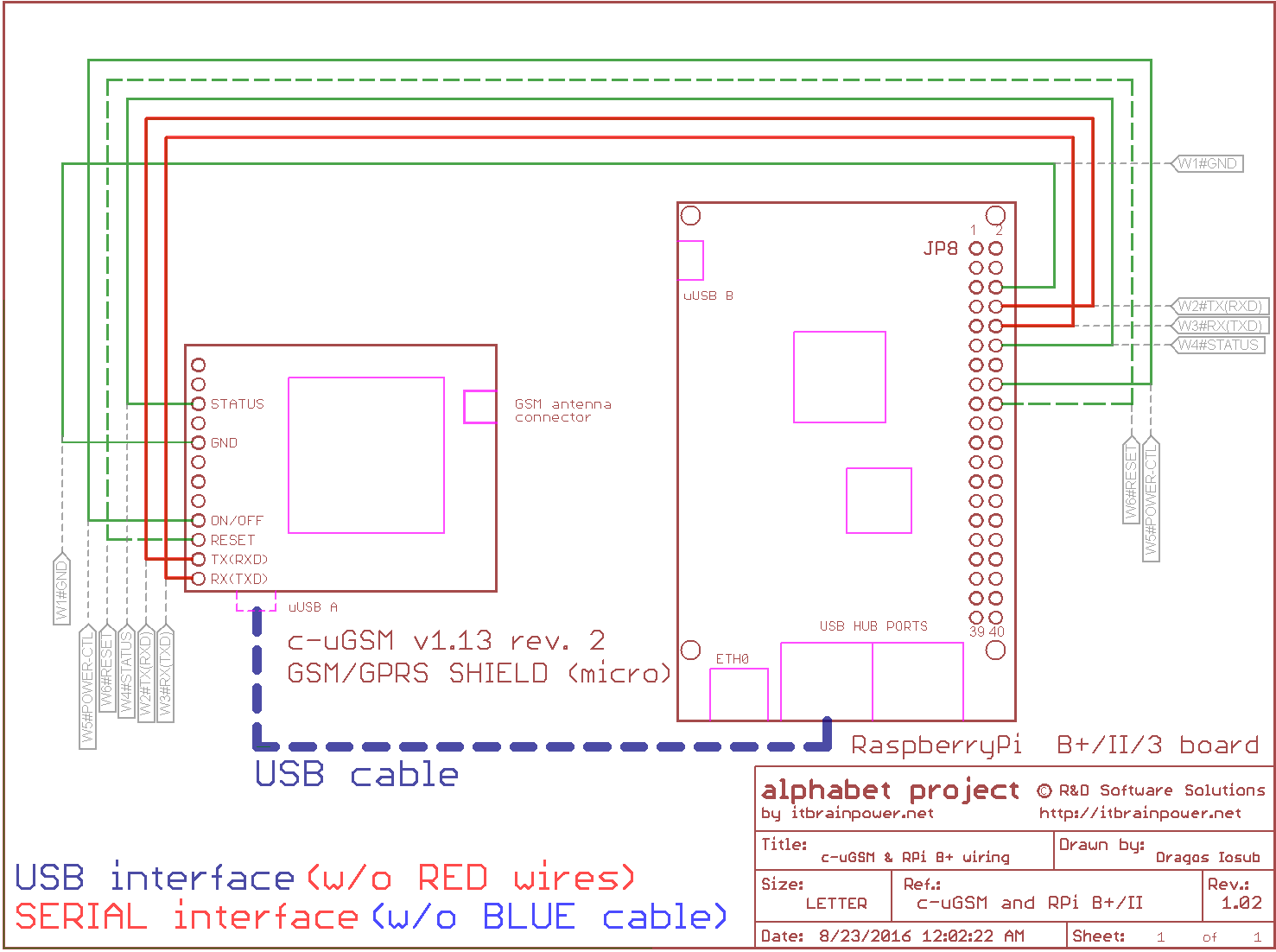
|
||||||||||||||||||||||||||||||||||||||||||||||||||||||||
| | ||||||||||||||||||||||||||||||||||||||||||||||||||||||||
Arduino Zero or xyz-mIoT modem-less shield interfacing:
1. RX(TXD) <-----> RX0 |
||||||||||||||||||||||||||||||||||||||||||||||||||||||||
| | ||||||||||||||||||||||||||||||||||||||||||||||||||||||||
c-uGSM - GSM shield (micro) :: ARDUINO & RASPBERRY PI CODE EXAMPLES and UTILITIES
Resources marked with "#", requires for download the following information: your name, email address and the modem IMEI. The modem IMEI can be found printed on the Quectel GSM module, or run AT+GMGS command. c-uGSM - GSM shield (micro) :: DOCUMENTATION DOWNLOADThe c-uGSM shield documentation can be found here. c-uGSM - GSM shield (micro) :: ARDUINO & RASPBERRY PI PROJECTSArduino & RaspberryPI projects based on itbrainpower.net products |
||||||||||||||||||||||||||||||||||||||||||||||||||||||||
c-uGSM - GSM shield (micro) :: ORDER ONLINEOrder online c-uGSM shield | ||||||||||||||||||||||||||||||||||||||||||||||||||||||||
c-uGSM - GSM shield (micro) :: ORDER FROM OUR DISTRIBUTORSChoose and order from one distributor near you. | ||||||||||||||||||||||||||||||||||||||||||||||||||||||||
the alphabet : order online a-gsmII shield [new] b-gsmgnss shield [new] a-gsm shield c-uGSM shield (micro) d-u3G shield (micro) f-audioOutputs adapter g-SPS boards i-hatGSM3G adapter j-328GSM3GLader adapter h-nanoGSM shield (nano) l-LTE shield s-Sense sensor breakout boards [HOT] u-GSM shield - CAT M1 / NB IoT / LTE [newest] xyz-mIoT integrated sensors IOT shield [newest] IoT product of week featured product [STRATUM1 NTP server] DOWNLOADS FAQs |
||||||||||||||||||||||||||||||||||||||||||||||||||||||||
|
Security, automation, monitoring, IoT and special purpose equipments: STRATUM 1 NTP server GNSS syncronized SMS gateway with parallel processing Temp., hum. and more monitor w. SMS alarm Development kits: LTE CATM + NB IoT development kit(s) Arduino and Raspberry PI how-to and tutorials hottest project newest project newest hardware how to newest software tutorial view all tutorials BME688 Arduino how to CCS811 Arduino how to HDC2010 Arduino how to BME680 Arduino how to BME280 Arduino how to BMP280 Arduino how to CCS811 RPI how to HDC2010 RPI how to BME680 RPI how to BME280 RPI how to BMP280 RPI how to Covid19 related resources: ZOOM speaker (w. Arduino shield and a-gsmII) - covid19 response help for elderly peoples PARP purified air flow controller for 12VDC blowers powered from 5V LiION power bank temperature, humidity and pressure sensor temperature and pressure sensor BME280 Arduino how to BMP280 Arduino how to BME280 RPI how to BMP280 RPI how to our environmental and air quality sensor breakouts: OPT3002 BME688 CCS811 + HDC2010 combo BME680 CCS811 BME280 BMP280 HDC2010 |
||||||||||||||||||||||||||||||||||||||||||||||||||||||||
|
distributors
contact
privacy policy
terms and conditions |
||||||||||||||||||||||||||||||||||||||||||||||||||||||||
| document version 1.101 / 2020-04-02 | © R&D Software Solutions srl | |||||||||||||||||||||||||||||||||||||||||||||||||||||||