About this tutorial
Atmel SAMD21G it's a very powerful ARM0 MCU included in Arduino Zero, xyz-mIoT by itbrainower.net and similar boards.
Even the MCU itself is quite powerful and versatile, when used with Arduino IDE, the MCU consumption in DEEP sleep mode is significant ~0.75 - 2.5mA - depending on board used and also dependent on MCU modules [Serial/Serial1/I2C/oscillators...] enabled by software application. This known limitation makes successful SAMD21G shields, as the one mentioned before, not to be the first choice for low power battery operated projects .... until now!
In this tutorial, I will show you what should be done to decrease the SAMD21G deep sleep mode power consumption, from 1-2mA down to a decent 35-37uA*.
* for sensor-less xyz-mIoT shields versions, including BG96, BC95G, M95FA modems and modem-less versions. For xyz-mIoT shields populated with sensors, all measured current values will be slightly higher.
* RTCC based and 1 pin interrupt wake up from deep sleep mode.
* precision crystal 32.768kHz oscillator [XOSC32K] was maintained in deep sleep for time accuracy.
* embedded xyz-mIoT LDO was not bypassed - the shield was powered via LiPO pads (Vbat and GND pins) at voltages between 3.3V and 4.2V.
* current measurements was performed, as global shield consumption, at 25degrees Celsius with all shield power supply chain (LiPO, LiION charger, LDO, ...) maintained..
As bonus, I will show you later how to decrease SAMD21G current consumption in run mode from ~10-12mA down to ~2.5mA!
Methods that are about to be reaveled in this article may be applied for battery powered, solar powered xyz-mIoT shields and also for classic wall powered solutions in order to decrease total IOT node power requirements.
Your IoT device will last for years powered by LiPO, LiION or Lithium batteries.
About xyz-mIoT shields
itbrainpower.net xyz-mIoT is a 35x45mm IoT shield built around ATSAMD21G ARM0 microcontroller (Arduino Zero compatible design) having embedded LiPO battery charger module, optional embedded THS + tVOC + HALL + IR + tilt/vibration sensors and optional LPWR LTE CATM1 or NB-IoT, 3G or GSM modem.
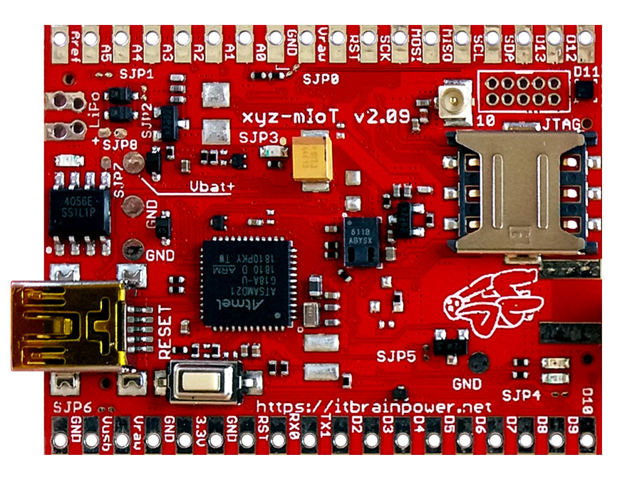
Driven by the power and versatility of the embedded ARM0 (ATSAMD21G) core and equipped with various interfaces [I2C, SPI, UART, 13 digital I/O - 1WIRE and PWM capable, 5 analog inputs and more - see specifications], "xyz-mIoT by itbrainpower.net" provides multiple interfaces in order to support wide range of devices, sensors and actuators.
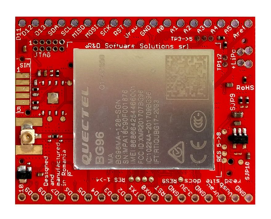
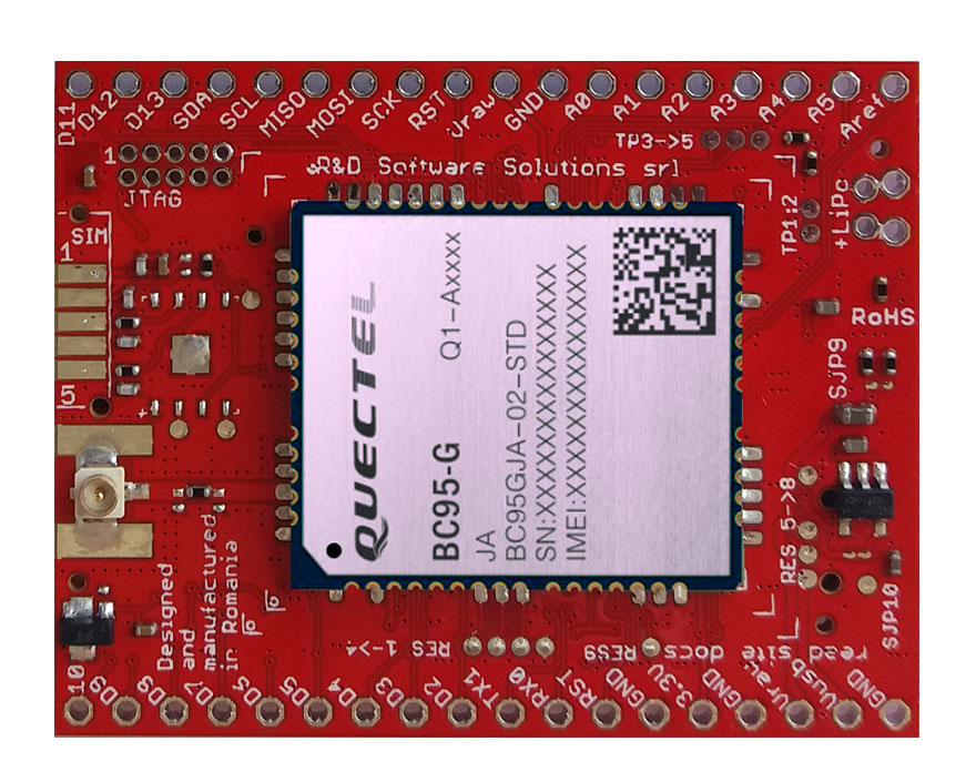
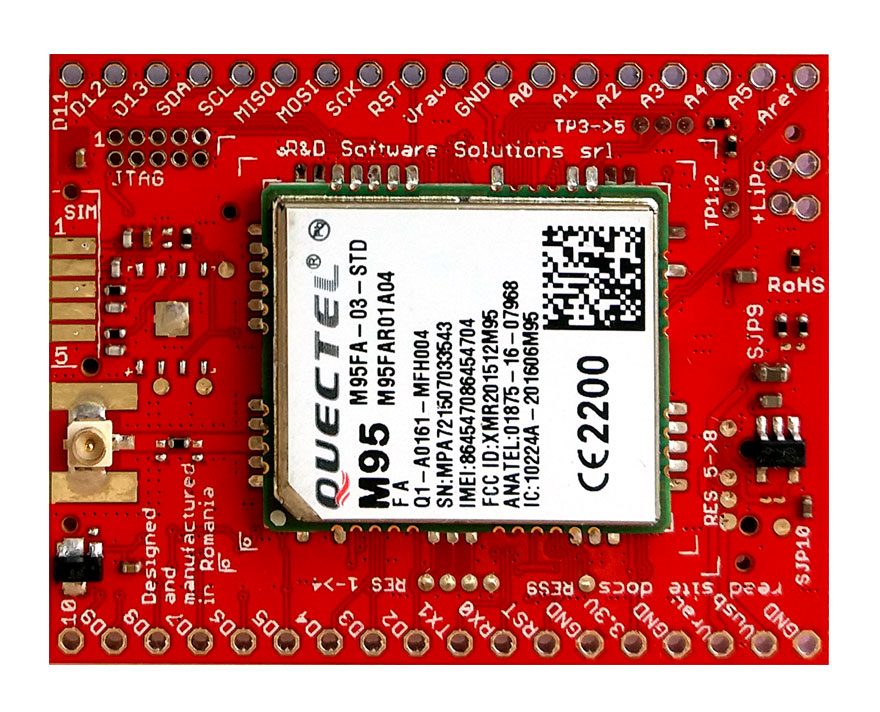
As modem capability classification, four main xyz-mIoT versions are curently commercially available: BG96 [LTE CATM1, NB IoT, 2G and GNSS], BC95G [NB IOT], M95FA [2G] and modemless - all having variants related to embedded sensor(s) integrated, see PN coding. Further more, xyz-mIoT design support other LTE CAT4, LTE CAT1 or 3G modem variants - if you require such variants for specific project, contact us.
The xyz-mIoT shield may have up to 5 built-in sensors such as: THS (temperature and humidity sensors) - HDC2010, tVOC & eCO2 (air quality sensor - CO2 total volatile organic compounds - CO2 equivalent) - CCS811, HALL (magnetic sensor) - DRV5032 or IR (infrared sensor) KP-2012P3C, secondary IR (infrared sensor) - KP-2012P3C, TILT (movement vibration sensor) - SW200D or REED (magnetic sensor). Based on populated sensors, several variants can be ordered using different Part Numbers, see PN coding.
xyz-mIoT hardware references
-
xyz-mIoT shield - specifications and PN coding
-
xyz-mIoT shield - pinout, port map and more
-
xyz-mIoT shield - block schematics
-
Microchip/Atmel ATSAMD21G - ARM0 microcontroller datasheet
-
other documentation, as: modems specification and AT manual, sensors datasheets, xyz-mIoT mechanical drawing and more.
-
xyz-mIoT SPI integration examples [ILI9341 240x320 TFT and SD reader].
-
xyz-mIoT UART0 integration example - [ESP12F - ESP8266MOD WIFI shield by AI-THINKER].
-
xyz-mIoT GPIO usage example - [SMS Relay controller].
and
-
xyz-mIoT powering reference.
Measured xyz-mIoT standard power consumption [from where we start]
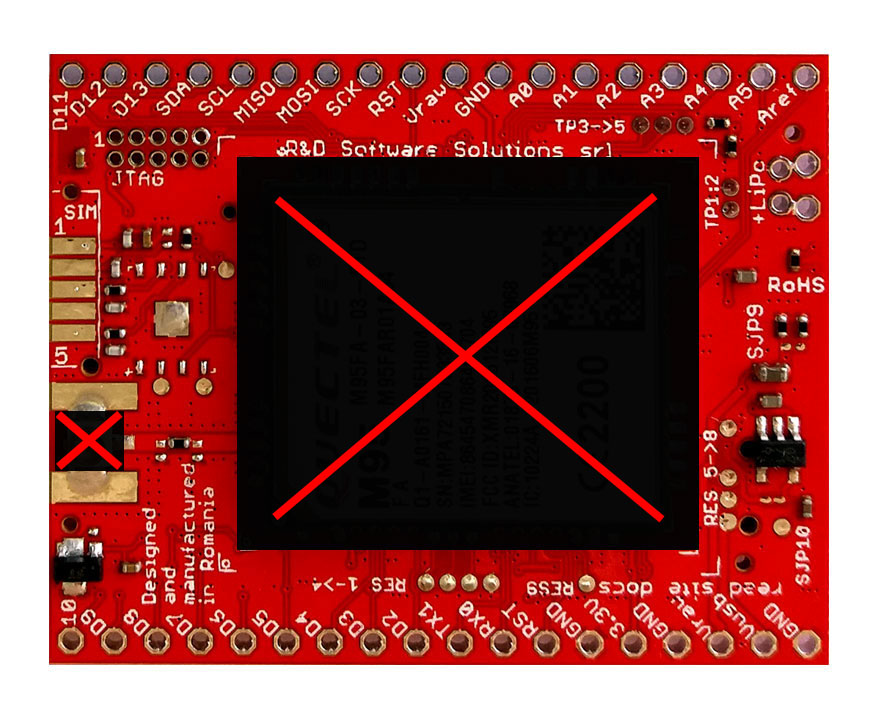
Image 1. Hardware circuit for consumption test [default powering for LiPO, LiION and Lithium primary batteries].

Default voltage used in test was 3.8V.
In image above is represented xyz-mIoT bare-bone [no modem], PN: XYZMIOT209#NOMODEM-000-0000000, but similar consumption results was obtained for xyz-mIoT shields with following part numbers: XYZMIOT209#BG96-UFL-0000000, XYZMIOT209#BC95G-UFL-0000000 and XYZMIOT209#M95FA-UFL-0000000.
SAMD21 RTCC SLEEP ALARM - Software used for run / sleep consumption test
| 1 | /* standard RTC sleep for SAMD21G, adapted for xyz-mIoT / SAMD21G current consumption measurements in RUN / SLEEP modes |
| 2 | * |
| 3 | * a. test without Serial and Serial1 software modules loaded |
| 4 | * b. test with Serial and Serial1 software modules loaded - remove comments on lines 52 and 53 |
| 5 | * |
| 6 | * |
| 7 | * Dragos Iosub, Bucharest 2020. |
| 8 | * https://itbrainpower.net |
| 9 | */ |
| 10 | |
| 11 | /* |
| 12 | Sleep RTC Alarm for Arduino Zero |
| 13 | |
| 14 | Demonstrates the use an alarm to wake up an Arduino zero from Standby mode |
| 15 | |
| 16 | This example code is in the public domain |
| 17 | |
| 18 | http://arduino.cc/en/Tutorial/SleepRTCAlarm |
| 19 | |
| 20 | created by Arturo Guadalupi |
| 21 | 17 Nov 2015 |
| 22 | modified |
| 23 | 01 Mar 2016 |
| 24 | |
| 25 | NOTE: |
| 26 | If you use this sketch with a MKR1000 you will see no output on the serial monitor. |
| 27 | This happens because the USB clock is stopped so it the USB connection is stopped too. |
| 28 | **To see again the USB port you have to double tap on the reset button!** |
| 29 | */ |
| 30 | |
| 31 | #include <RTCZero.h> |
| 32 | |
| 33 | /* Create an rtc object */ |
| 34 | RTCZero rtc; |
| 35 | |
| 36 | /* Change these values to set the current initial time */ |
| 37 | const byte seconds = 0; |
| 38 | const byte minutes = 00; |
| 39 | const byte hours = 17; |
| 40 | |
| 41 | /* Change these values to set the current initial date */ |
| 42 | const byte day = 17; |
| 43 | const byte month = 11; |
| 44 | const byte year = 15; |
| 45 | |
| 46 | void setup() |
| 47 | { |
| 48 | delay(5000); |
| 49 | pinMode(LED_BUILTIN, OUTPUT); |
| 50 | digitalWrite(LED_BUILTIN, LOW); |
| 51 | |
| 52 | //Serial.begin(9600); |
| 53 | //Serial1.begin(9600); |
| 54 | |
| 55 | rtc.begin(); |
| 56 | |
| 57 | rtc.setTime(hours, minutes, seconds); |
| 58 | rtc.setDate(day, month, year); |
| 59 | |
| 60 | rtc.setAlarmTime(17, 00, 10); |
| 61 | rtc.enableAlarm(rtc.MATCH_HHMMSS); |
| 62 | |
| 63 | rtc.attachInterrupt(alarmMatch); |
| 64 | |
| 65 | rtc.standbyMode(); |
| 66 | } |
| 67 | |
| 68 | void loop() |
| 69 | { |
| 70 | //blink once, show me MCU is in RUN mode |
| 71 | delay(500); |
| 72 | digitalWrite(LED_BUILTIN, LOW); |
| 73 | delay(500); |
| 74 | digitalWrite(LED_BUILTIN, HIGH); |
| 75 | delay(500); |
| 76 | digitalWrite(LED_BUILTIN, LOW); |
| 77 | |
| 78 | delay(5000); // intended for current consumption in RUN mode |
| 79 | |
| 80 | //blink twice, show me the MCU will enter SLEEP mode |
| 81 | digitalWrite(LED_BUILTIN, HIGH); |
| 82 | delay(500); |
| 83 | digitalWrite(LED_BUILTIN, LOW); |
| 84 | delay(500); |
| 85 | digitalWrite(LED_BUILTIN, HIGH); |
| 86 | delay(500); |
| 87 | digitalWrite(LED_BUILTIN, LOW); |
| 88 | |
| 89 | |
| 90 | rtc.setTime(hours, minutes, seconds); |
| 91 | rtc.setDate(day, month, year); |
| 92 | |
| 93 | rtc.standbyMode(); // Sleep until next alarm match, now you may sample the sleep current |
| 94 | } |
| 95 | |
| 96 | void alarmMatch() |
| 97 | { |
| 98 | digitalWrite(LED_BUILTIN, HIGH); |
| 99 | } |
| 100 |
Download above code (right click and save as) from: standardRTCSleepAlarm.ino. Download and use SAMD21G RTC library inside "xyz-mIoT shields RTCC and WDT Arduino classes" package, from: xyz-mIoT dwnload page.
Results for standard power profile
a. RUN mode, no UARTS enabled: 10.02mA
b. RUN mode, both UARTS enabled but idle: 11.38mA
c. SLEEP mode, no UARTS enabled / both UARTS enabled: 750uA / 1310uA
Shield USB must be not connected! Even this is not activated in software, USB will contribute with minimum 400uA at total shield consumption!
Next step, let patch the hardware around SAMD21G to prepared for low power scenario.
If your xyz-mIoT shield have the P/N with "-LPR" suffix (Eg.: "XYZMIOT209#M95FA-UFL-0000000-LPR") skip hardware preparation step and go directly to SAMD21G optimized low power software section.
This article is under update!
TUTORIAL PROVIDED WITHOUT ANY WARRANTY!!! USE IT AT YOUR OWN RISK!!!!