CONNECTION VARIANT B (FIXED)
Identify top/bottom sides and details on f-AudioOutpust.
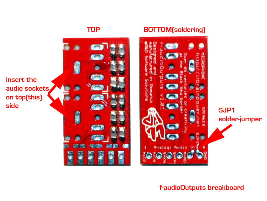
HINT: Over SJP1 solder jumper you must make soldered short-circuit (for c-uGSM shield usage). In this way, GND (digital ground) and AGND (analog ground) will be connected together.
I recommend to you to make this step after you solder the f-AudioOutputs board pinheader.
Insert and solder both Audio Jacks.
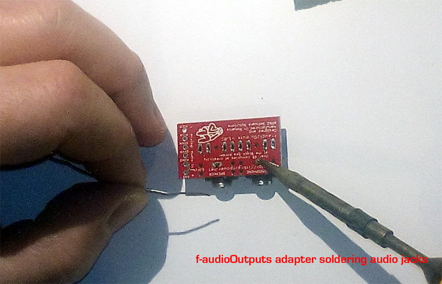
Both stereo audio sockets must be inserted on TOP side of the PCB. In picture above: bottom side, soldering the audio sockets.
Solder the pinheader on c-uGSM AUDIO INTERFACE.
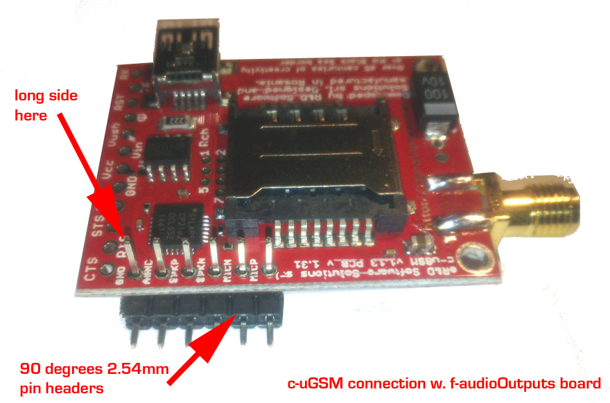
You may use 90 degree 0.1" (2.54mm) pinheaders, 6 pin. Observe the pinheader "long side" in above picture (leave the short side for f-AudioOutputs soldering). Above it is presented the horizontal option. For vertical mounting, use straight pinheaders in same idea.
Solder the pinheaders, then shorten the pinheaders usinf the cutter pliers (result bellow).
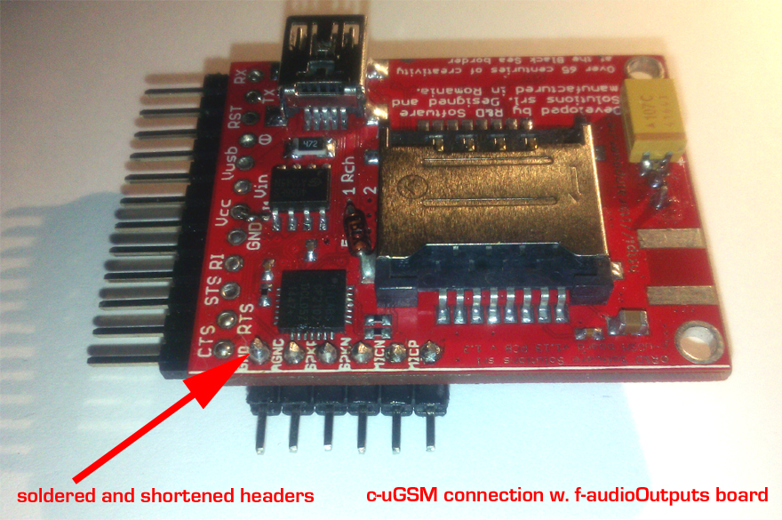
Prepare for and soldering the pinheader on f-AudioOutputs board adapter.
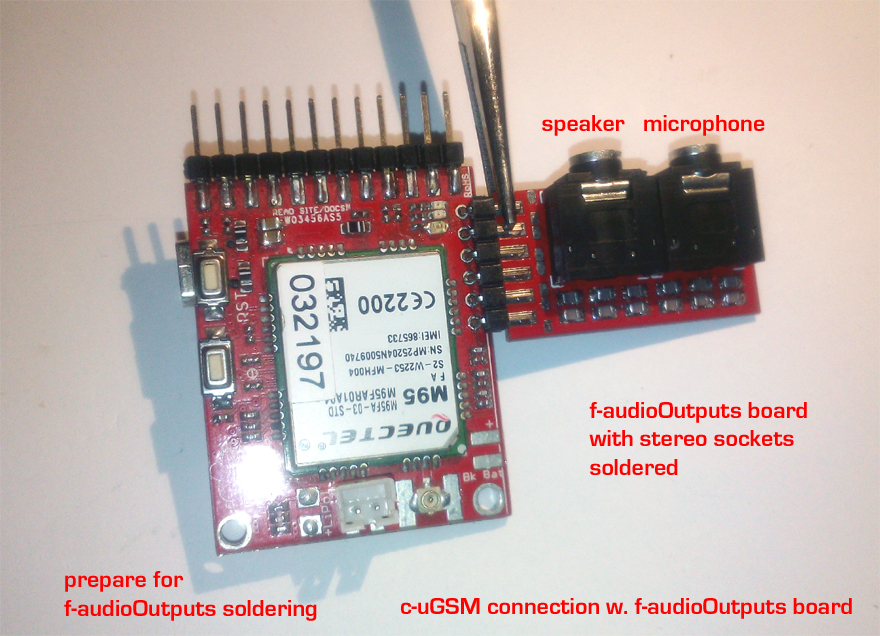
Fix the boards into position using the clamp/clip/pinch tool. Solder the pinheaders to the f-AudioOutputs PCB pads.
Make short-circuit to the SJP1 on f-AudioOutputs board adapter.
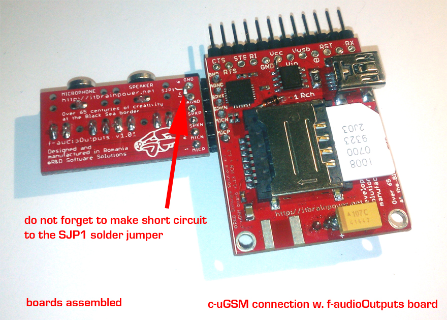
Check for short circuits before power the boards! READY!
You may like to see, into the previous page, the guide lines for "CONNECTION VARIANT A (REMOVABLE)".