itbrainpower.net
|
||||||||||||||||||||||||||||||||||||||||||||||||||||||||||||||||||
u-GSM shield :: FEATURES AT A GLANCE:Unique modem form factor that supports ALL existing GSM protocols [LTE CAT1.bis, LTE CAT M1, NB IoT, LTE CAT 4, LTE CAT 1, 3G/UMTS and 2G/GSM], depending on embedded module variant.Commercial PCB variants - RPI ready PCB or BBB & RPI PCB (available for certaign models):
Bellow, u-GSM variants: - u-GSM w. EG915U-EU - European LTE CAT1 + 2G - bands, protocols info and connectors order: ITBP-3070 - BBB & RPI PCB, uFL connector ITBP-3071 - RPI ready PCB, uFL connector ITBP-3072 - BBB & RPI PCB, SMA connector - u-GSM w. C16QS - European LTE CAT1.bis + GNSS - bands, protocols info and connectors order: ITBP-3060 - BBB & RPI PCB, uFL connector ITBP-3061 - RPI ready PCB, uFL connector ITBP-3062 - BBB & RPI PCB, SMA connector - u-GSM w. C17QS - GLOBAL LTE CAT1.bis + GNSS - bands, protocols info and connectors order: ITBP-3063 - BBB & RPI PCB, uFL connector ITBP-3064 - RPI ready PCB, uFL connector ITBP-3065 - BBB & RPI PCB, SMA connector - u-GSM w. EG95 - LTE CAT 4 + 3G/UMTS [+ GSM] * European version bands, protocols info and connectors order: ITBP-3001 - BBB & RPI PCB, uFL connector ITBP-3002 - BBB & RPI PCB, SMA connector *- North American version bands, protocols info and connectors order: ITBP-3005 - BBB & RPI PCB, uFL connector ITBP-3005 - BBB & RPI PCB, SMA connector - u-GSM w. EG91 - LTE CAT 1 + 3G/UMTS + GSM - bands, protocols info and connectors order: ITBP-3003 - BBB & RPI PCB, uFL connector ITBP-3004 - BBB & RPI PCB, SMA connector - u-GSM w. BG95-M3 - [Low Power LTE] CAT M1 + NB-IoT [CAT NB1 and NB2] + EGPRS + GNSS - bands, protocols info and connectors order: ITBP-3021 - BBB & RPI PCB, uFL connector ITBP-3022 - BBB & RPI PCB, SMA connector - u-GSM w. BG95-M2 - [Low Power LTE] CAT M1 + NB-IoT [CAT NB1 and NB2] + GNSS - bands, protocols info and connectors order: ITBP-3019 - BBB & RPI PCB, uFL connector ITBP-3020 - BBB & RPI PCB, SMA connector - u-GSM w. BG96 - [Low Power LTE] CAT M1 + NB-IoT + EGPRS + GNSS - bands, protocols info and connectors order: ITBP-3009 - BBB & RPI PCB, uFL connector ITBP-3010 - BBB & RPI PCB, SMA connector - u-GSM w. BC95G - [Low Power LTE] NB IoT - bands, protocols info and connectors order: ITBP-3011 - BBB & RPI PCB, uFL connector ITBP-3012 - BBB & RPI PCB, SMA connector - u-GSM w. M95FA - 2G / GSM / GPRS / EDGE - bands, protocols info and connectors - u-GSM w. UG96 & u-GSM w. UG95E - GLOBAL / EUROPEAN 3G/UMTS + [GSM] - retired More info about available versions and modem performances [bands, transfer speeds, protocols supported]: part numbers and description.
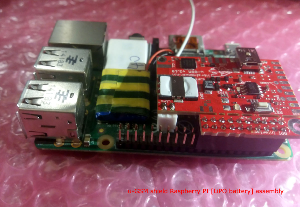
Raspberry PI embedded interface: Plug directly the u-GSM shield into Raspberry PI GPIO interface. Raspberry PI 5, 4, 3+, 3, II, B+, Zero and Zero W are supported. |
||||||||||||||||||||||||||||||||||||||||||||||||||||||||||||||||||
u-GSM shield :: INTERFACES, SWITCHES and CONNECTORS
    ITBPMM INTERFACEIn the left edge of the top PCB side, bottom to top:1. RX[TXD] - modem TX - output 2. TX[RXD] - modem RX - input 3. RST - MODEM RESET - input, active HIGH* 4. ENA - ENABLE MODEM POWER - input, active HIGH** 5. Vusb - POWER PIN - output +5V (USB +5V) 6. Vin - POWER PIN - input +5V for LiPol charger only 7. Vcc - POWER PIN - input/output +4V** 8. GND - POWER and DIGITAL GROUND 9. RI - RING INDICATOR - output 10. STATUS - STATUS - output * min. 250msec. pulse [HIGH level] will RESET the modem, excepting BG95-Mx, BG96 and EG915U-xx variants. RST pin have alternate functionality, as POWER ON / POWER OFF / exit PSM mode, for BG95-Mx and BG96 variants and POWER ON / POWER OFF, for EG915U-xx variants. ** HIGH level will enable modem power. All u-GSM variants, excepting BG95-Mx, BG96 and EG915U-xx, will be waked [POWERED ON]. ** LOW level disconnects the modem power. All u-GSM variants will shutdown. *&** To wake BG95-Mx, BG96 and EG915u-xx variants, keep ENA pin to HIGH level and then apply 250-500ms HIGH level pulse to RST pin. Raspberry PI embedded interfaceIn the PCB top side left hand, from left to right:RPI02 - Vin <--> RPI 5V* RPI04 - Vin <--> RPI 5V* RPI06 - GND <--> RPI GND RPI08 - TX[RXD] <--> RPI SERIAL TX** RPI10 - RX[TXD] <--> RPI SERIAL RX** RPI12 - STS <--> RPI GPIO18 RPI16 - ENA <--> RPI GPIO23 RPI16 - RST <--> RPI GPIO24 * Read about sjp7 functionality bellow. ** Read about sjp5 and sjp6 functionality bellow. BeagleBone Black embedded interfaceIn the PCB top side right hand, from right to left:P9.01 - GND <--> BBB GND P9.02 - GND <--> BBB GND P9.05 - Vin <--> VDD 5V* *** P9.06 - Vin <--> VDD 5V* *** P9.11 - RX[TXD] <--> GPIO_30[UART4_RXD]** P9.12 - RST <--> GPIO_60 P9.13 - TX[RXD] <--> GPIO_31[UART4_TXD]** P9.15 - ENA <--> GPIO_50 P9.16 - STS <--> GPIO_51 * Read about sjp7 functionality bellow. ** Read about sjp5 and sjp6 functionality bellow. LEDs, switches and additional interfacesPCB top edge, left to right:1. RST switch - RESET function for all versions, excepting BG95-Mx, BG96 and EG915U-xx. POWER ON / POWER OFF / exit PSM mode for BG95-Mx and BG96 variants. POWER ON / POWER OFF for EG915U-xx variants. 2. GREEN LED - network status LED 3. YELLOW LED - power status LED 4. GNSS u.FL connector [only for BG95-Mx, BG96, EG95A variants] 5. LiPO / LiION battery connector [GND, +] Left PCB side, inside PCB, from top to bottom: 1. GND - super-capacitor soldering PAD, negative pole 2&3. Vbat - super-capacitor soldering PADs, positive pole PCB bottom edge, from left to right: 1. USB connector type miniB 2. USB soldering PADS [GND, D-, D+, Vusb] Right PCB edge: 1. nano SIM socket connector Solder jumperssjp1* - RESERVED - default circuit closed.sjp2 - Active GNSS antenna powering - default, the active GNDD antenna power is enabled [circuit closed]. Relevant only for BG95-Mx, BG96 and EG95A variants. sjp3 - disable LEDs powering - default, LEDs power is enabled [circuit closed]. STS [STATUS] signal is disabled if LEDs power is disabled. sjp4 - bypass modem power separation - default disabled [circuit open]. If enabled, ENA input will lose its role. sjp5 and sjp6 - connect modem UART to RPI and BBB embedded interfaces - default connected [circuits closed]. If disconnect, RPI/BBB RX and TX GPIOs will be released. You may like to use this option if modem is connected to RPI/BBB via USB. sjp7* - connect Vin to BBB/RPI 5V - default connected - u-GSM us as power supply 5V from RPI / BBB [circuit closed]. If disconnect, u-GSM may be powered independent. BBB voltage selector* - use BBB Vdd 5V / SYS 5V as power source - default Vdd 5V is used as power source. Relevant if u-GSM is connected with BBB. sjp5, sjp6, sjp7 and BBB voltage selector are relevant only if u-GSM is connected to BBB/RPI via embedded interfaces. * consult u-GSM block schema. External SIM CARD port, antenna connectorExternal SIM card interface 1. SIM VDD 2. SIM DATA 3. SIM RESET 4. SIM GND 5. SIM CLOCK - if not used, leave them not connected - if used, in order to avoid interferences, keep the wires as short as possible and take in to account the routing. GSM side antenna connector u-GSM shield may be ordered with u.FL connector or with SMA F connector. Check here: u-GSM part numbers. PCB breaking linesIf required the u-GSM PCB may be trimmed across the breaking lines. We recommend to you to trim the u-GSM PCB only if you intend to fit your Raspberry PI & u-GSM shield assembly into one RPI case.Guidelines here. |
||||||||||||||||||||||||||||||||||||||||||||||||||||||||||||||||||
| | ||||||||||||||||||||||||||||||||||||||||||||||||||||||||||||||||||
u-GSM shield :: Arduino / Raspberry PI logical interfacing [using ITBPMM interface] |
||||||||||||||||||||||||||||||||||||||||||||||||||||||||||||||||||

|
||||||||||||||||||||||||||||||||||||||||||||||||||||||||||||||||||
Arduino Zero or xyz-mIoT modem-less shield interfacing:
1. RX(TXD) <-----> RX0 |
||||||||||||||||||||||||||||||||||||||||||||||||||||||||||||||||||
| | ||||||||||||||||||||||||||||||||||||||||||||||||||||||||||||||||||
u-GSM shield :: Raspberry PI logical interfacing [using Raspberry PI embedded interface] |
||||||||||||||||||||||||||||||||||||||||||||||||||||||||||||||||||
|
||||||||||||||||||||||||||||||||||||||||||||||||||||||||||||||||||
| | ||||||||||||||||||||||||||||||||||||||||||||||||||||||||||||||||||
u-GSM shield :: BeagleBone Black logical interfacing |
||||||||||||||||||||||||||||||||||||||||||||||||||||||||||||||||||
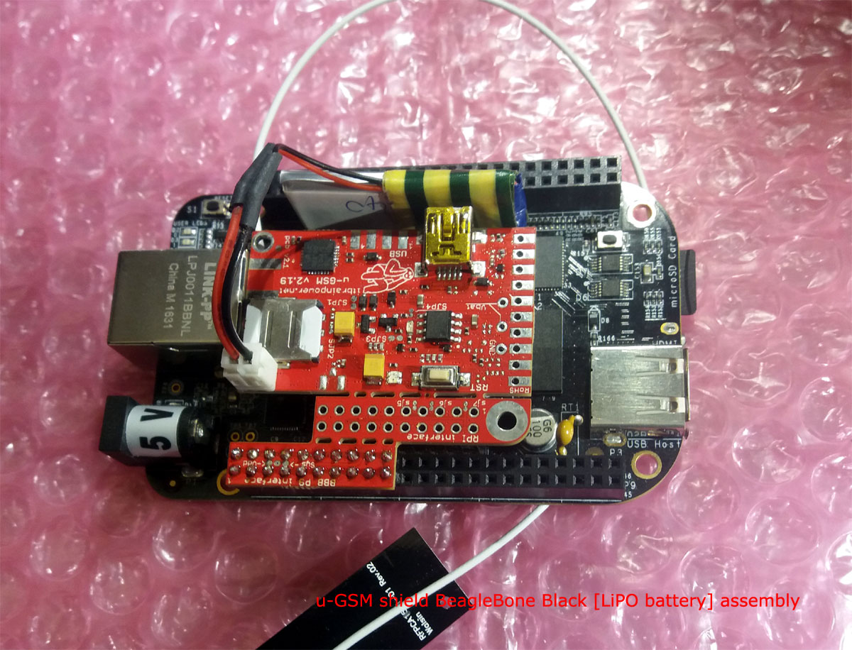
Variant a. Interfacing using BeagleBone Black P9 embedded interface |
||||||||||||||||||||||||||||||||||||||||||||||||||||||||||||||||||
| | ||||||||||||||||||||||||||||||||||||||||||||||||||||||||||||||||||
u-GSM shield :: ARDUINO, BeagleBone & RASPBERRY PI CODE EXAMPLES and UTILITIES
Resources marked with "#", requires for download the following information: your name, email address and the modem IMEI. The modem IMEI can be found printed on the Quectel GSM module, or run AT+GMGS command. u-GSM shield :: DOCUMENTATION DOWNLOAD/ONLINEThe u-GSM shield documentation can be found here. u-GSM shield :: ARDUINO, BEAGLEBONE & RASPBERRY PI PROJECTSArduino & RaspberryPI projects based on itbrainpower.net products |
||||||||||||||||||||||||||||||||||||||||||||||||||||||||||||||||||
u-GSM shield :: ORDER ONLINEOrder online u-GSM shield | ||||||||||||||||||||||||||||||||||||||||||||||||||||||||||||||||||
u-GSM shield :: ORDER FROM OUR DISTRIBUTORSChoose and order from one distributor near you. | ||||||||||||||||||||||||||||||||||||||||||||||||||||||||||||||||||
the alphabet : order online a-gsmII shield [new] b-gsmgnss shield [new] a-gsm shield c-uGSM shield (micro) d-u3G shield (micro) f-audioOutputs adapter g-SPS boards i-hatGSM3G adapter j-328GSM3GLader adapter h-nanoGSM shield (nano) l-LTE shield s-Sense sensor breakout boards [HOT] u-GSM shield - CAT M1 / NB IoT / LTE [newest] xyz-mIoT integrated sensors IOT shield [newest] IoT product of week featured product [STRATUM1 NTP server] DOWNLOADS FAQs |
||||||||||||||||||||||||||||||||||||||||||||||||||||||||||||||||||
|
Security, automation, monitoring, IoT and special purpose equipments: STRATUM 1 NTP server GNSS syncronized SMS gateway with parallel processing Temp., hum. and more monitor w. SMS alarm Development kits: LTE CATM + NB IoT development kit(s) Arduino and Raspberry PI how-to and tutorials hottest project newest project newest hardware how to newest software tutorial view all tutorials BME688 Arduino how to CCS811 Arduino how to HDC2010 Arduino how to BME680 Arduino how to BME280 Arduino how to BMP280 Arduino how to CCS811 RPI how to HDC2010 RPI how to BME680 RPI how to BME280 RPI how to BMP280 RPI how to Covid19 related resources: ZOOM speaker (w. Arduino shield and a-gsmII) - covid19 response help for elderly peoples PARP purified air flow controller for 12VDC blowers powered from 5V LiION power bank temperature, humidity and pressure sensor temperature and pressure sensor BME280 Arduino how to BMP280 Arduino how to BME280 RPI how to BMP280 RPI how to our environmental and air quality sensor breakouts: OPT3002 BME688 CCS811 + HDC2010 combo BME680 CCS811 BME280 BMP280 HDC2010 |
||||||||||||||||||||||||||||||||||||||||||||||||||||||||||||||||||
|
distributors
contact
privacy policy
terms and conditions |
||||||||||||||||||||||||||||||||||||||||||||||||||||||||||||||||||
| document version 1.31 / 2026-04-15 | © R&D Software Solutions srl | |||||||||||||||||||||||||||||||||||||||||||||||||||||||||||||||||

